|
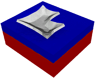
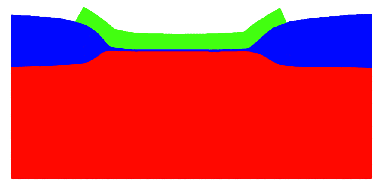
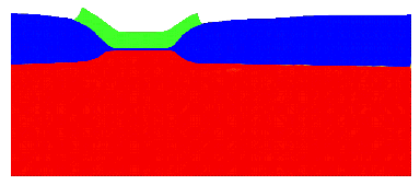
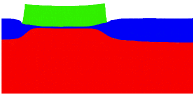
The next step was to attack a more complicated situation with adequate interface conditions. Fig 5.9 shows the three-dimensional geometry where an oxidation process has been calculated. The problem in this example arises on the one hand just because of the more complex geometry and on the other hand from the floating nitride layer. Whereas in the previous examples the nitride was fixed with a moving boundary condition that reduces the freedom of the system, now this condition can not be used because it leads to a more unstable total system. Nevertheless, the introduced model is capable to handle this vicious case in an acceptable manner, too. The interface of the material has now been calculated with a level set function parameter of ac = 1050. That declares the more realistic results because of the immediate jump from zero to one at the interface between silicon and silicon dioxide. Also the initial pad oxide was used for a more realistic example. The deformation of the nitride mask was again calculated with an elasto-mechanical model. Due to the enormous size of the model itself (eight coupled quantities) no more than 17376 node points putting up 41421 elements have been used to calculate the oxidation process. Nevertheless, due to the grid adaptation algorithm it was possible to get quite acceptable results. The post-processed cuts through the layer shown in Fig. 5.10 and Fig. 5.11 depict the familiar oxidation results firstly at the longer side of the mask and secondly at the shorter one.
|
|
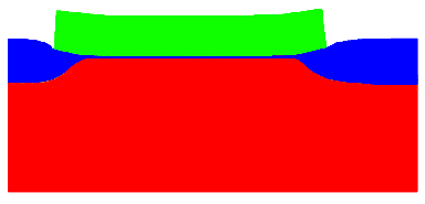
Fig. 5.12 shows the same calculation but with a four times thicker nitride mask. The fact that now the mask can hardly be deformed leads to high stresses beneath the nitride mask, and because of the viscous material behavior of oxide the deformation of the formed oxide layer differs in form and size (Fig. 5.13 and Fig. 5.14) from the previous examples.
|
|