2.4 Data Structure for Meshes
As mentioned in the introduction, one goal of this work is to optimize memory requirements of meshes. Therefore, a simple data structure for multi-region mesh is presented in this section which will later be used for memory usage comparison. The programming language C is used to define the data structures as C provides a common interface for a plethora of other programming languages.
Let
 be an
be an  -dimensional mesh and
 be an
be an  -dimensional multi-region mesh to be stored in memory: The data structure of
 and
and
 are defined as shown in Listing 2.1 and Listing 2.2, respectively.
![\begin{lstlisting}[caption={Mesh data structure},label={src:mesh_datastructure}]...
...l_vertex_indices[];
INDEX_TYPE cell_vertex_index_offsets[];
};
\end{lstlisting}](img485.gif)
![\begin{lstlisting}[caption={Multi-region mesh data structure},label={src:multire...
...]
struct MRMESH
{
MESH mesh;
REGION_ID_TYPE cell_region[];
};
\end{lstlisting}](img486.gif)
Figure 2.13:
Mesh data structure layout
|
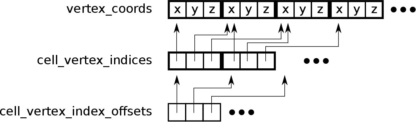
The vertices are stored in the linear coordinate array vertex_coords illustrated in the top. For each cell, the indices of all of its vertices are stored in the cell_vertex_indices array. The cell_vertex_index_offsets is used to determine the first and the last vertex index for each cell in the cell_vertex_indices array. The cell_types and cell_region arrays are simple linear buffers and not visualized in this illustration. |
The only difference between these two mesh data structures is the cell_region array, which is present in the multi-region mesh data structure but not in the other one.
The storage layout of the data structures, illustrated in Figure 2.13, is motivated by the compressed sparse row format for sparse matrices [141].
Usually, IEEE 754 32-bit single or 64-bit double floating point types [1] are used as
NUMERIC_TYPE.
For each vertex
 ,
,  numerical values are stored. Therefore the vertex coordinate array has a size of
 .
.
A cell
 is defined using an identifier for its element type and a tuple of indices for each boundary vertex
 . Only element types which can be uniquely defined using a tuple of boundary vertices can be used with this method.
For example, a generic non-convex polyhedron cannot be defined by using only its boundary vertices.
However, all elements presented in this work support this method.
The element type identifier can be represented by an integer value with the size (in bits) equal to the binary logarithm of number of different element types, rounded up. A total of eight different element types are used in this work, so the size of an element type identifier is at least three bits. However, due to memory aliasing issues and to avoid bit shifting operations, an eight bit integer data type is used as ELEMENT_TYPE.
The vertex index tuples of each cell are stored sequentially in the cell vertex index array using an arbitrary ordering of the cells.
. Only element types which can be uniquely defined using a tuple of boundary vertices can be used with this method.
For example, a generic non-convex polyhedron cannot be defined by using only its boundary vertices.
However, all elements presented in this work support this method.
The element type identifier can be represented by an integer value with the size (in bits) equal to the binary logarithm of number of different element types, rounded up. A total of eight different element types are used in this work, so the size of an element type identifier is at least three bits. However, due to memory aliasing issues and to avoid bit shifting operations, an eight bit integer data type is used as ELEMENT_TYPE.
The vertex index tuples of each cell are stored sequentially in the cell vertex index array using an arbitrary ordering of the cells.
The starting index for the  -th cell is stored in the cell vertex index offset array at location
  .
Therefore, the number of vertices for the
.
Therefore, the number of vertices for the  -th cell is equal to cell_vertex_index_offsets[i+1] - cell_vertex_index_offsets[i]. For convenience, the cell vertex index offset array has a size equal to the number of cells plus one. The last entry of the cell vertex index offset array is the total number of all vertex indices of all cells. INDEX_TYPE is an integer type with at least
  bits. A
  bit integer type is only required for meshes with more than
  vertices.
For each cell in a multi-region mesh, there is an additional region identifier which is stored in the cell region array. Depending on the maximum number of regions supported, REGION_ID_TYPE is an integer type with either
vertices.
For each cell in a multi-region mesh, there is an additional region identifier which is stored in the cell region array. Depending on the maximum number of regions supported, REGION_ID_TYPE is an integer type with either  ,
,  , or
, or  bits. Meshes with more than
  regions are very rare, thus a
  bit integer is used.
A configuration with NUMERIC_TYPE being a
bit integer is used.
A configuration with NUMERIC_TYPE being a  bit double floating point type, ELEMENT_TYPE being an
  bit integer type, INDEX_TYPE being a
  bit integer type, and REGION_ID_TYPE being a
  bit integer type is used in this work.
The total memory usage of a mesh mainly depends on the number of its cells and vertices.
For meshes with only one cell type, like simplex meshes or all-quad meshes, the number of boundary vertices per cell can be trivially determined for all cells of the mesh. Therefore, the size of the cell vertex index array can be calculated.
However, only an upper bound can be given for mixed meshes.
Therefore, the upper bound for the memory usage (in byte) of a mesh
 and a multi-region mesh
 in
in
 is given by:
 |
(2.5) |
 |
(2.6) |
The variables point_dimension, vertex_count, and cell_count are not covered by that formula, because their size in memory is negligible.
florian
2016-11-21