

Next: 9.3.4 Handling Multiple Devices
Up: 9.3 Inverse Modeling of
Previous: 9.3.2 Modeling the Doping
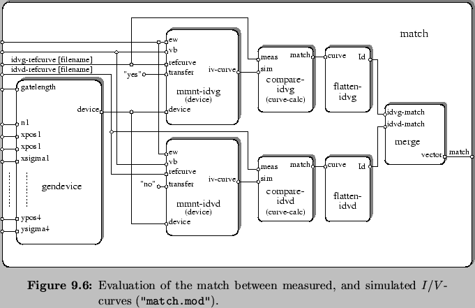
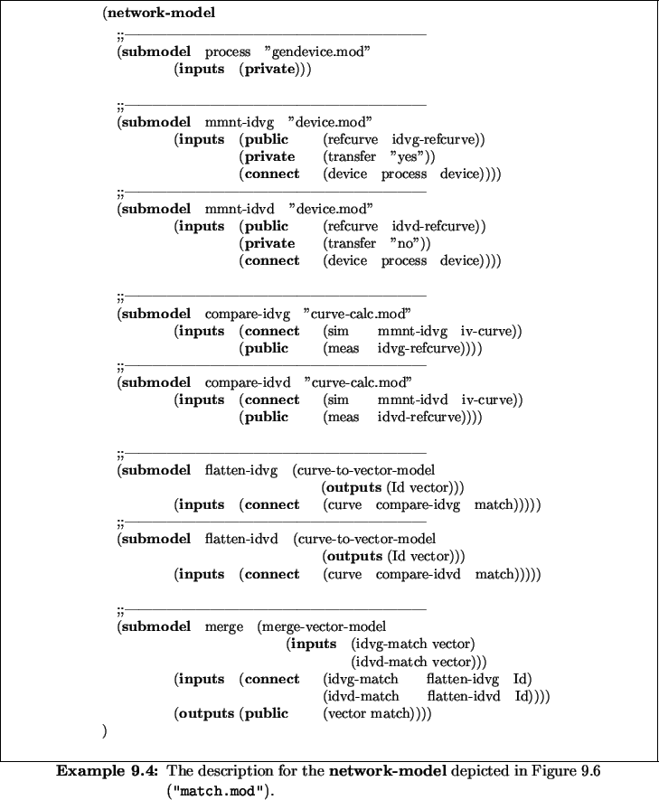
The network-model described by Example 9.4 and depicted
in Figure 9.6 quantifies the match for the transfer
(ID/VG), and output curves (ID/VD) for the NMOS device produced by
the simulation-flow-model designed before. It uses MINIMOS-NT for this purpose,
which is encapsulated by a simulation-flow-model
("device.mod"). MINIMOS-NT offers a nice feature to read the
sequence of operating points to be simulated, which constitute a
desired I/V-curve, from a preexisting I/V-curve. Since this
model has to compare these curves to the measured I/V-curves, we
use the settings of the measurements to control the MINIMOS-NT device
simulator. Thus, we derive simulated I/V-curves which are structurally
identical to their measured equivalent.
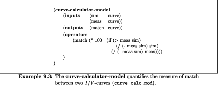
The actual comparison is done by the curve-calculator-model
("curve-calc.mod") described by Example 9.3. It
defines the measure of match as
which delivers values between
![$[ +100\mbox{\%}, -100\mbox{\%}]$](img132.gif) .
The
output of the curve-calculator-model is a curve which contains this
measure of match for each operating point of the measured curve.
.
The
output of the curve-calculator-model is a curve which contains this
measure of match for each operating point of the measured curve.


As next step we convert this structured representation of the match
into the flat representation of a vector of floating point numbers. We
do this by means of the curve-to-vector-models labeled
flatten-idvg, and flatten-idvd. These models
convert the curve column known as Id into a vector. Finally,
we concatenate these two vectors into a single one by means of a
merge-vector-model, which is labeled merge and thus obtain
the result of the network-model at the output port named
match.


Next: 9.3.4 Handling Multiple Devices
Up: 9.3 Inverse Modeling of
Previous: 9.3.2 Modeling the Doping
Rudi Strasser
1999-05-27

