Figure 4.4:
(a) Alignment of constant-energy surfaces of the Si conduction band
with respect to the (111) substrate surface. (b) Projection of
constant-energy surfaces onto the (111) plane. Since the quantization mass is
equal for all valleys, only one sixfold degenerate subband ladder is formed.
[a] ![\includegraphics[scale=1.0]{inkscape/Cut111_2.eps}](img778.png)
[b] ![\includegraphics[scale=1.5]{inkscape/projectionOr111.eps}](img779.png)
|
The substrate normal
 for substrate orientation
(111) is
for substrate orientation
(111) is
 . Thus, the axes of the principal
crystallographic systems have to be rotated by the angles
. Thus, the axes of the principal
crystallographic systems have to be rotated by the angles
 (
(
 ) and
) and
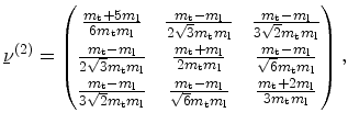
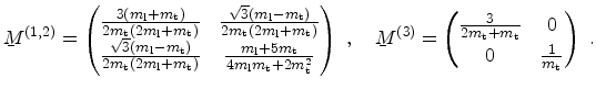
 . The inverse effective mass tensor for the three
valley pairs in the coordinate system with the
. The inverse effective mass tensor for the three
valley pairs in the coordinate system with the  axis perpendicular
to the substrate surface are
axis perpendicular
to the substrate surface are
 |
(4.25) |
 |
(4.26) |
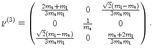 |
(4.27) |
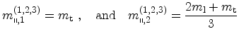
It can be seen that all valleys have the same quantization mass
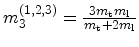 and therefore belong to the same subband ladder.
To determine the transport masses, the eigenvalues of
and therefore belong to the same subband ladder.
To determine the transport masses, the eigenvalues of
 have to be
calculated
have to be
calculated
 |
(4.28) |
Solving the secular equation (4.15) the transport masses evaluate to
 |
(4.29) |
for all three valley pairs.
The constant-energy lines of the subbands for a (111) substrate are shown in
Figure 4.4b. The unprimed ladder is sixfold degenerate. Two ladders have
their major principal axes parallel to the
![$ [11\bar{2}]$](img790.png) direction. The
principal axes of the other ladders is inclined by an angle of
direction. The
principal axes of the other ladders is inclined by an angle of  and
and
 from
from
![$ [\bar{1}10]$](img777.png) .
.
In Table 4.1 the principal effective masses of Si for the three
discussed surface orientations are summarized. In unstrained Si the six
conduction band valleys form a set of two subband ladders for substrate
orientation (001) and (110), whereas for (111) oriented substrate only
one subband ladder with sixfold degeneracy is formed. The energy alignments of
the Si conduction subband ladders constituting on (001), (110), and
(111) oriented substrate are shown Figure 4.5a and
Figure 4.5b.
Table 4.1:
Principal effective masses of the six Si conduction
band minima along  for three surface orientations. Here,
 , and
, and
 denote the transport masses,
and
denote the transport masses,
and  is the quantization mass.
| surface orientation |
degeneracy |
|
|
 |
ladder |
| |
2 |
 |
|
 |
unprimed |
| |
4 |
|
|
|
| |
4 |
|
 |
 |
unprimed |
| |
2 |
|
|
|
| (111) |
6 |
|
 |
 |
unprimed |
|
|
|
|
|
|
|
E. Ungersboeck: Advanced Modelling Aspects of Modern Strained CMOS Technology