The scope of this section is restricted to symmetric second order tensor fields defined on a tetrahedral grid [52]:
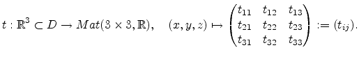 |
(A.16) |
The idea is to reinterpret the covariance matrix depicted in
Equation (A.15) as symmetric tensor of second order. Literature
provides a wide spectrum of different implementations, for the
visualization of tensor fields, for e.g. see [128]
and [129]. Among the simplest are tensor glyphs, because the shape and
orientation of glyph geometry indicates eigenvalues and eigenvectors in one
diagram [130]. Glyphs are pointed on discrete
locations compared to other visualization techniques, like texture-based
methods such as Line Integral Convolution (LIC) [131]. Other
methods, like hyper-streamlines, integrate tensor eigenvectors and thus
represent particular continuous field features [132].
For the visualization of the anisotropic property of tetrahedra an ellipsoidal glyph is used, because glyphs can be placed on any discrete location. The general ellipsoid, also called triaxial ellipsoid, is a quadratic surface which is given in Cartesian coordinates by
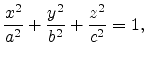 |
(A.17) |
where the semi-axes are of lengths ![]() ,
, ![]() , and
, and ![]() . The volume of an
ellipsoid is given by
. The volume of an
ellipsoid is given by
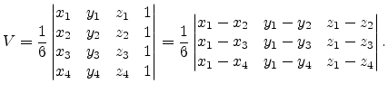
Back to the tetrahedron depicted in Figure A.1 the volume is given by
The reinterpretation of the ellipsoidal semiaxis ![]() ,
,![]() , and
, and ![]() by the
eigenvectors scaled by the corresponding eigenvalues yields the glyph
visualization. Since glyphs are three-dimensional objects, they should not
overlap and their spatial expansion should be judiciously scaled. For
a good ratio between the glyph and the tetrahedron the scaling was chosen that
both objects have the same volume with respect to Equation (A.18) and
Equation (A.19). The center of the ellipsoid was placed in the
center of gravity of the tetrahedron.
Figure A.2 illustrates the
principal component analysis based on the ellipsoidal glyph visualization procedure
applied to two tetrahedra which are part of explanations in
Section 2.3.
by the
eigenvectors scaled by the corresponding eigenvalues yields the glyph
visualization. Since glyphs are three-dimensional objects, they should not
overlap and their spatial expansion should be judiciously scaled. For
a good ratio between the glyph and the tetrahedron the scaling was chosen that
both objects have the same volume with respect to Equation (A.18) and
Equation (A.19). The center of the ellipsoid was placed in the
center of gravity of the tetrahedron.
Figure A.2 illustrates the
principal component analysis based on the ellipsoidal glyph visualization procedure
applied to two tetrahedra which are part of explanations in
Section 2.3.
![\begin{figure*}\centering
\subfigure[Anisotropy.]
{\epsfig{figure=pics/PCA-Nee...
...psfig{figure=pics/PCA-Regular.eps2,height=0.25\textwidth} }% \\
\end{figure*}](img597.png) |