5.4 Threading dislocation density in heterostructures
In this section a model for the evolution of threading dislocations in GaN-based multilayers
is derived by integrating Mathis’ model [49] with the model of Romanov [66]. The
impact of the hexagonal symmetry is considered with an appropriate expression for the
misfit dislocation density [24,31]. In the first Paragraph 5.4.1 of this section, appropriate
equations describing the motion of one isolated dislocation are derived. Then in
Paragraph 5.4.2, the reaction-kinetic approach introduced by Romanov [64] is used to
quantify the probability that two threading dislocations come in contact with each other. A
model describing the threading dislocation density with increasing film thickness in
multilayers is described through a set of differential equations (see Paragraph 5.4.3). These
are then applied to a bilayer (Paragraph 5.4.5) in order to evaluate which parameters have
the strongest impact on the results. After this, the threading dislocation density is
calculated in a step-graded layer and superlattice to understand which structure is
better for minimizing the threading dislocation population (Paragraph 5.4.6).
Concluding the section, various design rules for dislocation filter are deduced and listed.
5.4.1 Motion of an isolated TD
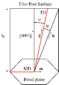
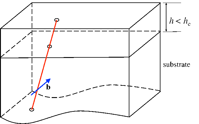
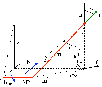
An isolated threading dislocation is depicted in Figure 5.12.
An uniformly strained layer of thickness hf is epitaxially bonded to a substrate of
relatively larger thickness. The normal to the film-substrate interface is denoted by nf. The
equibiaxial mismatch strain until critical thickness is denoted by ϵm. A threading dislocation
is assumed to exist along a particular glide plane in the presence of the background
mismatch strain field. The threading dislocation line extends from the free surface of the
film to the substrate. The tangent vector of the threading dislocation is denoted l. During
the film growth, it is assumed that the threading dislocation geometry remains self-similar.
This means that the threading dislocation remains in the position of minimum energy with
constant line direction l. The Burgers vector of the threading dislocation is denoted
by b. The slip plane of the dislocation (the plane containing the dislocation line
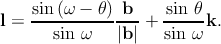
and the Burgers vector) is defined by its normal ng. The angle α between the
dislocation line l and the normal nf of the free surface is calculated according to the
minimization of the dislocation energy in Chapter 3. Therefore l can be derived from the
relation:
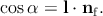 | (5.8) |
ψ is defined as the angle between k and the projection of k to the film/substrate
interface [65]:
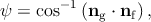 | (5.9) |
where k is defined as [65]
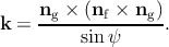 | (5.10) |
The angle ω is defined as [65]
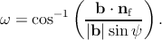 | (5.11) |
After the vector k and the angle ω are calculated using the previous relations, the angle
between b and the threading dislocation line l is denoted as θ, and can derived
by [65]
 | (5.12) |
During film growth, if film thickness is below the critical value, the threading dislocation is
sessile, i.e., it is not able to glide. As a consequence, the threading dislocation does not move
physically but the threading dislocation upper point moves along the free surface due to the
inclination of the threading dislocation with respect to the growth direction. According to
Figure 5.12, the point of intersection of the threading dislocation with the free surface
of the film moves with direction f along the free surface. The velocity vS of the
upper point of one sessile threading dislocation along the free surface is calculated
as [65]:
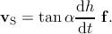 | (5.13) |
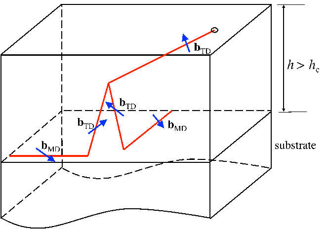
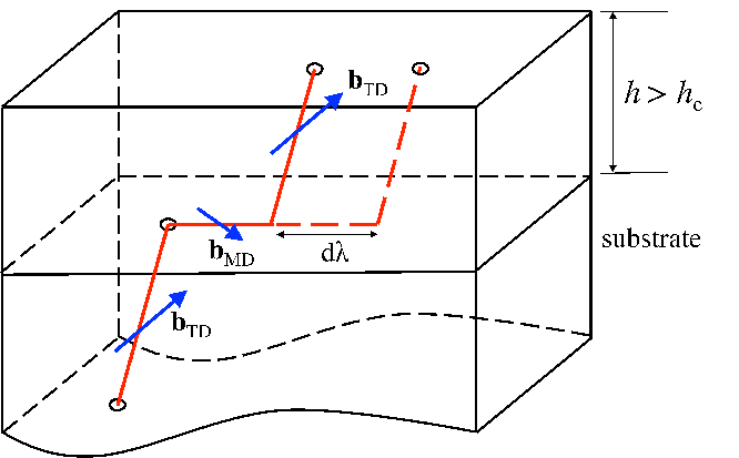
As the film thickness increases after the critical thickness, the relaxation of the misfit stress
occurs via the glide of the threading dislocation, which leaves behind one misfit segment
along the interface. This misfit segment is generally called misfit dislocation and its length is
denoted λ in this work. The misfit dislocation elongates until the complete relaxation of the
misfit strain and the direction m of the elongation is the direction of the gliding threading
dislocation [65]:
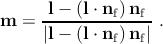 | (5.14) |
In this work, the portion of the dislocation spanning the film thickness is still called the
threading dislocation segment, or simply the threading dislocation. During the film growth
after the critical thickness, λ increases as a result of relaxation of the initial misfit
strain εm, causing a further glide of the threading segment. Concurrently, the
threading dislocation length increases due to the increase of the film thickness.
Thus after the critical thickness is reached, the threading dislocation intersection
with the free surface will move not only due to the (eventual) inclination with
respect to the free surface but also as a result of the threading dislocation glide, i.e.,
the misfit dislocation elongation along the interface. In other words, the upper
point of the threading dislocation moves due to the inclination of the threading
dislocation with respect to the free surface but also moves physically as a result of the
threading dislocation glide along the interface. Therefore, the upper point of a
glissile threading dislocation (i.e., a dislocation able to glide) has a velocity defined
of
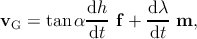 | (5.15) |
where the first term takes the motion due to the inclination with respect to the film free
surface into account, and the second term the motion due to the elongation of the misfit
segment.
The elongation of the misfit segment is related to the relaxation of the structure caused
by the film growth after the critical value. In order to establish a relation between the misfit
dislocation elongation dλ and the increase of the film thickness dh, it is necessary to
consider the expression for the misfit dislocation density (denoted as ρMD) reported in
Section 5.3.
For the isotropic system, the differentiated form of expression (5.4) with respect to h
is
For the hexagonal system, the differentiated form of expression (5.6) with respect to h
is
Misfit dislocations are generated through the motion of glissile threading dislocations, so it
is possible to give a second definition of ρMD as a function of the total density ρG of the
glissile threading dislocations:
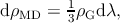 | (5.18) |
where the factor 1∕3 accounts for the use of a linear misfit dislocation density in a
hexagonal grid array of misfit dislocations. When combining expression (5.16) or
expression (5.17) with expression (5.18), and solving for dλ, the result is that
dλ = Cdh∕(h2ρ
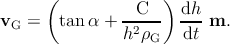
G), with C = 3Ciso or C = 3Chex. Substituting the last relation in
expression (5.15), the velocity of the glissile threading dislocation is expressed
as
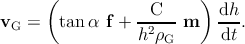 | (5.19) |
5.4.2 Reactions among dislocations
Two threading dislocations with different Burgers vectors bi and bj and line directions li
and lj are considered. The two threading dislocations can be either glissile or sessile.
Supposing that the film thickness is increasing, the upper points of the two threading
dislocations move along the film free surface until the point they come within a distance r
such that the interaction forces are sufficient to initiate additional motion of dislocations.
They can now start to react with each other. The driving force for the interaction
between dislocations is the minimization of the internal energy. Three possible
reactions (annihilation, fusion, and scattering) can occur depending on Frank’s
criterion (see equation (5.3)). The interaction radius r within which all these
reactions occur is intended to be the same value in this work [49]. The probability of
reaction between these threading dislocations at any point on the free surface is
supposed to be uniform and occur with a reaction rate of V ij. This is defined
as a function of the difference between the velocities vi and vj of the threading
dislocations [49]:
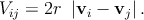 | (5.20) |
The velocities are calculated properly for sessile and glissile threading dislocations through
expressions (5.13) and (5.19), respectively.
Using 5.20 as well as the reaction kinetic approach introduced by Romanov [64], it is
possible to describe how the threading dislocation density changes during epitaxial growth.
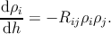
The densities of the i-th and j-th threading dislocation families are indicated with ρi
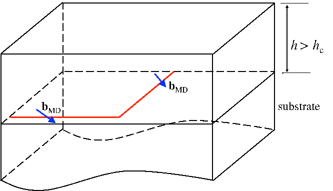
and ρj respectively. If annihilation or fusion occur between dislocations of i-th
and j-th kinds, then the diminishing density for the i-th kind can be calculated
by [49]
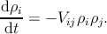 | (5.21) |
and a similar expression can be written for the density of the j-th kind threading
dislocations. When multiplying both the members of the previous equation by dt and
combining with expressions (5.19) and (5.20), (5.21) becomes
 | (5.22) |
where
Rij = 2r  . . | | (5.23) |
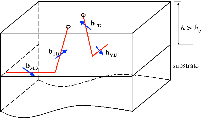
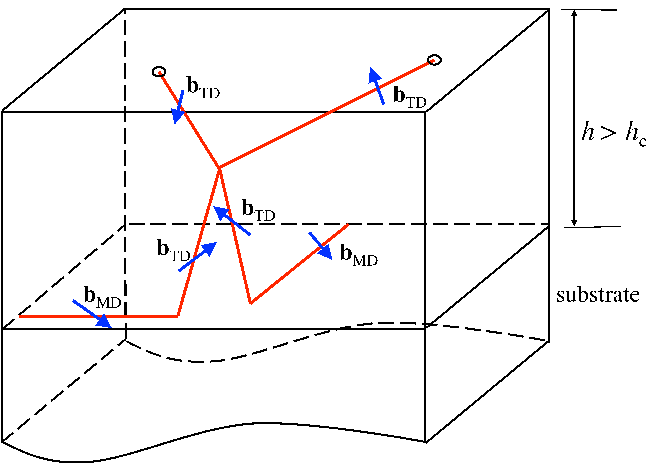
Fusion reactions between the i-th and j-th threading dislocations also have the effect of
producing a new threading dislocation of the k-family; therefore a production term is taken
into account for each kind of threading dislocation:
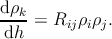 | (5.24) |
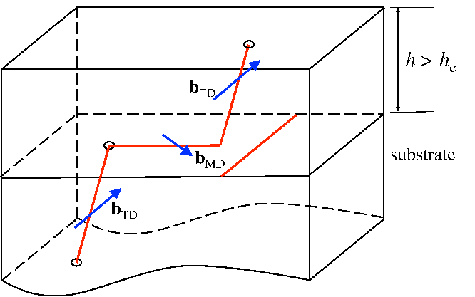
Scattering reactions between the i-th and j-th threading dislocations can produce two k-th
threading dislocations (see the reaction Table 5.1); therefore the previous equation is
corrected as
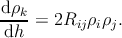 | (5.25) |
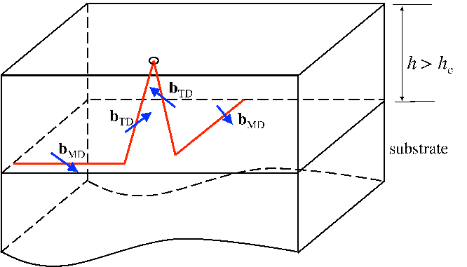
In general, the evolution of density ρk of dislocations belonging to the k-th family with the
film thickness is described by
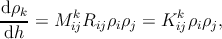 | (5.26) |
where Mijk = 0 in case of annihilation, M
ijk = 1 (k≠i and k≠j) for fusion and
scattering reactions, and Mijk = 2 (k≠i and k≠j) for scattering reactions that
produce two threading dislocations belonging to the same ρk family (see the reaction
Table 5.1).
5.4.3 Sessile and glissile dislocations
Until now, the evolution of the dislocation density was described independently from the
ability of the dislocation to glide or not. As discussed previously, when the film thickness is
lower than its critical thickness, all threading dislocations are unable to glide along the
substrate-film interface. Therefore, all threading dislocations are sessile before reaching the
critical thickness. In hexagonal structures there are 20 threading dislocation families (see
Section 5.2). Since each threading dislocation can be glissile or sessile above the critical
thickness depending on the above mentioned conditions, there are 20 families of
glissile threading dislocations and 20 families of sessile threading dislocations. The
densities of these two groups are evaluated separately in the subsequent treatment. In
particular, the rate Rij is denoted RG,ij in the case where threading dislocations are
glissile, RS,ij both the threading dislocations are sessile or RGS,ij when one threading
dislocation is glissile and the other sessile. Similarly, Kijk is denoted K
G,ijk in the
case where both threading dislocations are glissile, KS,ijk when both threading
dislocations are sessile or KGS,ijk when one threading dislocation is glissile and the other
sessile.
The total density of threading dislocations, i.e., the number of threading dislocations per
unit area of the free surface, is indicated with ρTD, the total density of sessile
threading dislocations and the total density of glissile threading dislocations are
indicated with ρS and ρG respectively. Therefore, below the critical thickness we
have
| ρTD = ρS = ∑
k=120 ρ
S,k. | | (5.27) |
Above the critical thickness, it is assumed that each threading dislocation can glide,
becoming glissile and leaving a misfit segment behind. Consequently, the total density of
threading dislocations is the sum of sessile and glissile threading dislocation densities. If ρG
indicates the total density of glissile threading dislocations, above the critical thickness this
results in
| ρTD = ρG + ρS = ∑
k=120 ρ
G,k + ∑
k=120 ρ
S,k. | | (5.28) |
Changing the film thickness by dh, the previous expression becomes
 = ∑
k=120 = ∑
k=120  + ∑
k=120 + ∑
k=120  . . | | (5.29) |
The complete relaxation of the structure stops the threading dislocation glide, and glissile
threading dislocations become sessile again. Considering equation (5.19), the complete
relaxation is reached when vG reduces to vS for h →∞.
In parallel, other factors can stop the dislocation glide above the critical thickness and
before the saturation point. During the motion, one glissile threading dislocation may be
blocked by a misfit segment lying in the path of another moving threading dislocation, as
shown schematically in Figure 5.4.3. The problem of threading dislocation blocking was
treated in detail by Freund [18]. In the present treatment, once a threading dislocation
has been blocked by a crossing misfit dislocation, its motion will be considered
arrested for all further film growth. The chance of intersection of a randomly located
glissile threading dislocation with a misfit dislocation is supposed to be ρG,kρMDdh.
The result is a decrease of the density of k-type glissile threading dislocations
by
| dρG,k = -ρG,kρMDdh, | | (5.30) |
and consequently the density of the k-type sessile threading dislocations increases
by
| dρS,k = ρG,kρMDdh. | | (5.31) |
Also the reactions among threading dislocations can affect the ratio between glissile and
sessile dislocations. The number of glissile dislocations decreases when two glissile threading
dislocations annihilate each other and therefore the density of k-type glissile threading
dislocations is decreased by the following:
dρG,k = -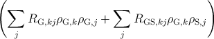 dh. dh. | | (5.32) |
Annihilation is not the only reaction which decreases the density of glissile dislocations. Few
experimental observations of the interaction between a glissile and a sessile dislocations are
available in literature. Thus it is assumed in this work that the motion of one glissile
dislocation ends when it encounters another threading dislocation (either glissile or sessile).
At this point, the two threading dislocations react with each other by fusion or scattering
and the resulting dislocation/dislocations remains/remain sessile. The density decreases
by
dρG,k = -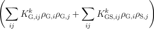 dh. dh. | | (5.33) |
In parallel, the density of k-type sessile threading dislocations increases by
dρS,k =  dh. dh. | | (5.34) |
Based on equations (5.30), (5.32), and (5.33), by increasing the film thickness
by dh, the total variation of the density of k-type glissile threading dislocations
is
 = = | - ρG,k ρMD | |
|
| -∑
j RG,kj ρG,k ρG,j -∑
j RGS,kj ρG,k ρS,j | |
|
| -∑
ij KG,ijk ρ
G,i ρG,j -∑
ij KGS,ijk ρ
G,i ρS,j. | (5.35) |
The number of sessile threading dislocations is increased by the decrease of the glissile
threading dislocation density (see equations (5.31) and (5.34)). In addition the reactions
among sessile threading dislocations affect the density of the k-type sessile threading
dislocation:
dρS,k = 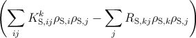 dh. dh. | | (5.36) |
The k-type sessile threading dislocations can annihilate with glissile dislocations of an
another family, therefore
dρS,k = -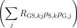 dh. dh. | | (5.37) |
Based on equations (5.31), (5.34), (5.36), and (5.37), by increasing the film thickness
by dh, the total variation of the density of k-type sessile threading dislocations
is
 = = | + ρG,k ρMD | |
|
| + ∑
ijKG,ijk ρ
G,i ρG,j + ∑
ijKGS,ijk ρ
G,i ρS,j | |
|
| + ∑
ijKS,ijk ρ
S,i ρS,j -∑
jRS,kj ρS,k ρS,j | |
|
| -∑
jRGS,kj ρS,k ρG,j. | (5.38) |
The variation of ρTD with the film thickness dh is obtained by combining expression (5.29)
with expressions (5.17), (5.35) and (5.38):
 = = | ∑
k=120  + ∑
k=120 + ∑
k=120  , , | (5.39)
|
 = = | - ρG,k ρMD | |
|
| -∑
j RG,kj ρG,k ρG,j -∑
j RGS,kj ρG,k ρS,j | |
|
| -∑
ij KG,ijk ρ
G,i ρG,j -∑
ij KGS,ijk ρ
G,i ρS,j, | (5.40) |
 = = | + ρG,k ρMD | |
|
| + ∑
ijKG,ijk ρ
G,i ρG,j + ∑
ijKGS,ijk ρ
G,i ρS,j | |
|
| + ∑
ijKS,ijk ρ
S,i ρS,j -∑
jRS,kj ρS,k ρS,j | |
|
| -∑
jRGS,kj ρS,k ρG,j, | (5.41)
|
 = = |   dh = dh =  . . | (5.42) |
The calculation of the total density of the threading dislocation is performed with the
software Wolfram Mathematica for the heterostructures considered in the next
Paragraphs.
5.4.4 Initial and boundary conditions
In this section the initial and boundary conditions used to solve the system
of equations defined by equations (5.29), (5.17), (5.35) and (5.38) are listed.
- A single-crystal structure of Al1-xGaxN oriented along the
![[0001]](DISS530x.png) direction
is considered. The values of the lattice parameters of GaN and AlN are
aGaN=3.22Å, cGaN=5.19Å, aAlN=3.11Å, and cAlN=4.98Å respectively. The values
for the Al1-xGaxN alloy are calculated using Vegard’s law [76].
direction
is considered. The values of the lattice parameters of GaN and AlN are
aGaN=3.22Å, cGaN=5.19Å, aAlN=3.11Å, and cAlN=4.98Å respectively. The values
for the Al1-xGaxN alloy are calculated using Vegard’s law [76].
- The core radius of each threading dislocation is supposed to be half of its Burgers
vector.
- Anisotropic elasticity is used to calculate the critical thickness and the misfit
dislocation density; consequently, C=Chex (see equation (5.17)).
- The interaction radius is 40nm [79].
- The importance of the inclination angle for the calculation of the dislocation
density was discussed in Section 5.2.1. The equilibrium values for the inclination
angle were calculated in Section 3.7. According to this calculation, in
![[0001 ]](DISS531x.png) GaN
all types of threading dislocation are parallel to the
GaN
all types of threading dislocation are parallel to the ![[0001 ]](DISS532x.png) direction. In reality,
experimental observations show that this angle is influenced by many factors not
considered in this work, such as temperature, island growth, doping, masking,
and misfit stress relaxation. Mathis [49] and other authors [22] observed that
a- and c-type threading dislocations are parallel to the
direction. In reality,
experimental observations show that this angle is influenced by many factors not
considered in this work, such as temperature, island growth, doping, masking,
and misfit stress relaxation. Mathis [49] and other authors [22] observed that
a- and c-type threading dislocations are parallel to the ![[0001 ]](DISS533x.png) direction but the
(a + c) type threading dislocations are inclined by 12∘. Holec [25] showed how
the island-growth mode can bend threading dislocations in the proximity of
inclined facets. Cantu [7] grew Si doped Al0.49Ga0.51N films upon Al0.62Ga0.38N
and observed inclined dislocations in the film. The inclination was suggested to
be caused by the Si doping. Li [43] arrived at the same conclusion by doping
a GaN-based film with Mg. In contrast to their explanations, Follstaedt [16]
and coauthors realized that in similar structures, dislocations are bent before the
introduction of any dopant. According to him, the relaxation of the misfit stress
causes the bending. In this work, the screw and edge threading dislocations in
GaN are supposed to be aligned with the
direction but the
(a + c) type threading dislocations are inclined by 12∘. Holec [25] showed how
the island-growth mode can bend threading dislocations in the proximity of
inclined facets. Cantu [7] grew Si doped Al0.49Ga0.51N films upon Al0.62Ga0.38N
and observed inclined dislocations in the film. The inclination was suggested to
be caused by the Si doping. Li [43] arrived at the same conclusion by doping
a GaN-based film with Mg. In contrast to their explanations, Follstaedt [16]
and coauthors realized that in similar structures, dislocations are bent before the
introduction of any dopant. According to him, the relaxation of the misfit stress
causes the bending. In this work, the screw and edge threading dislocations in
GaN are supposed to be aligned with the ![[0001]](DISS534x.png) direction, and the (a + c)-type
threading dislocations inclined with respect to it (like assumed by Mathis [49]).
Based on these experimental findings, the inclination angle is assumed to be very
small (5∘). The reason for this comes from evaluating the threading dislocation
density in an unfavorable condition, i.e., the reaction probability is minimum.
direction, and the (a + c)-type
threading dislocations inclined with respect to it (like assumed by Mathis [49]).
Based on these experimental findings, the inclination angle is assumed to be very
small (5∘). The reason for this comes from evaluating the threading dislocation
density in an unfavorable condition, i.e., the reaction probability is minimum.
- It is also assumed that the planar growth mode prevents threading dislocation
inclination due to the vicinity with the inclined facets.
- The initial amount of threading dislocations is set at 1010cm-2 as reported
by different authors [38, 56, 81]. The initial threading dislocation density is
composed of 70% a-type threading dislocation and 30% (a + c)-type threading
dislocation. Different ratios are evaluated in Section 5.4.5.
- Several authors [39, 49] show that c-type dislocations are not very mobile
and not capable of reacting with other dislocations. Different explanations for
this behavior have been proposed. The c-type dislocation oriented along the
![[0001]](DISS535x.png) direction is a screw dislocation. It might happen, for example, that screw
dislocations exist at the center of a growth hillock or at the center of a nanopipe.
In the case of a growth hillock, mixed dislocations must elongate and move across
the hillock to reach the screw dislocation, making reactions less likely.
direction is a screw dislocation. It might happen, for example, that screw
dislocations exist at the center of a growth hillock or at the center of a nanopipe.
In the case of a growth hillock, mixed dislocations must elongate and move across
the hillock to reach the screw dislocation, making reactions less likely.
- A major assumption of the present model is a simplification of the geometry of the
dislocation glide. It is assumed that a misfit segment and the upper point of a
threading dislocation have the same direction, i.e., they have the same velocity
f = m (see Figure 5.14), and equation (5.19) for glissile dislocations reduces
to
 | (5.43) |
As a consequence, it is assumed that only the (a + c)-type threading dislocations have
the possibility to move, being that they are the only ones tilted with respect to the
growth direction, the only ones to execute lateral motion toward each other and the
only ones to react with an increase in the layer thickness. Despite this simplification,
the model brings some insight and, although not quantitatively, at least qualitatively
accounts for the contribution of glide to the threading dislocation density
reduction.
5.4.5 GaN/AlN bilayer
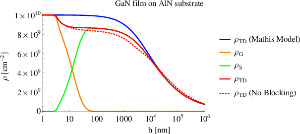
The model described in Section 5.4 is used to calculate the threading dislocation density
as a function of the film thickness hf in a [0001] GaN film grown upon a AlN
substrate. The results (red line in Figure 5.15) are compared with those from Mathis’
model [49] (blue line in Figure 5.15). The initial and boundary conditions are listed in
Paragraph 5.4.4.
The development of the threading dislocation density according to Mathis can be divided
into three stages, like as with semipolar bulk GaN (see Section 5.2.1). Initially, the density
remains quite constant because no reactions occur due to the big distance among
dislocations. After 1μm, the density decreases due to threading dislocation reactions. When
all dislocations having reacted, their density assumes an asymptotical value, reaching the
saturation point at 1mm.
The threading dislocation density according to the model proposed in this work is
represented by the red solid line in Figure 5.15. This can be divided into five
stages.
-
1.
- Initially the density remains constant because dislocations are too far from each
other to react.
-
2.
- After the critical thickness is reached, which is 3μm according to Steeds [72],
dislocations glide along the interface and this causes the reactions. Therefore, the
threading dislocation density decreases in the 10nm above the critical thickness.
As a result of the threading dislocation glide, the density is 15% less with respect
to what was predicted by Mathis.
-
3.
- After hf = 15nm, the density is quite constant because dislocations not longer
glide (since the misfit stress is totally relaxed) but reactions driven by threading
dislocation inclination do not take place until 1μm.
-
4.
- After hf = 1μm, reactions caused by threading dislocation inclination occur,
which decreases the density until the point the model reduces to the Mathis
model at hf = 10μm.
-
5.
- For hf > 10μm, the behavior is equal to that of the Mathis model.
Experimental observations (from private discussions with Dr. Baumgartl) confirm that the
presence of the interface and the subsequent glide of the dislocations decreases the threading
dislocation density. Therefore, the improved model agrees better with the experimental
observations respect to the Mathis’ model.
The red dotted line in Figure 5.15 represents the threading dislocation density
– according to the model described in this work – without threading dislocation blocking
caused by the presence of misfit dislocations along the interface. The red solid and dotted
lines are close to each other meaning that threading dislocation blocking is negligible. This
means that the first term from the left sides of both equations (5.35) and (5.38) is
negligible.
In the following, the threading dislocation density for the same bilayer – GaN film upon
AlN substrate – is calculated, thus the initial conditions are changed.
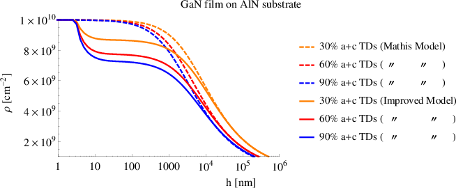
One assumption is that only (a + c)-type threading dislocations are capable of gliding. In
order to increase the impact of the glide, the initial amount of (a + c)-type threading
dislocations is raised from 30% up to 60% and 90%. The related results are shown in
Figure 5.16. When the initial threading dislocation density is composed of 90% of
(a + c)-type threading dislocations, the final density is reduced by 30% with respect
to the value given by Mathis’ model for hf < 2μm. Instead, for hf > 2μm, the
variation of the initial amount of (a + c)-type threading dislocations has a negligible
impact.
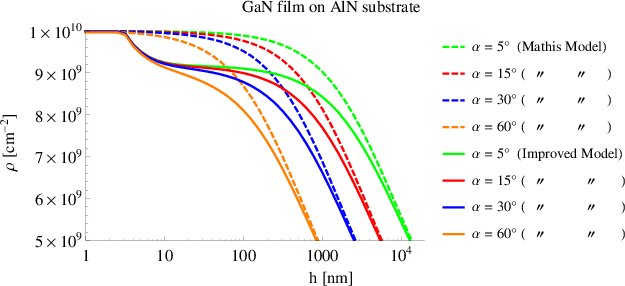
The effect of the inclination angle α is evaluated keeping the other initial and boundary
conditions equal to those reported in Section 5.4.4. Both Mathis’ model and the improved
one are used to calculate the threading dislocation density for different values of α.
Figure 5.17 shows that the variation of α becomes remarkable in both models at higher
thicknesses. At hf = 1μm, the threading dislocation density with α = 60∘ is halved with
respect to the case with α = 5∘. The models confirm that increasing the inclination angle –
by island growth, doping, and strain relaxation – drastically improves the quality of the
crystalline structure.
In conclusion, the crystalline quality of GaN film grown upon an AlN thicker layer is
improved by increasing the inclination angle rather than other factors. The dislocation glide
decreases the threading dislocation density only by 15% with respect to what was predicted
by Mathis’ model for bulk structures. The presence of one interface is ineffective in reducing
the dislocation density. The main goal now is to evaluate the impact of the glide in a more
complex heterostructure, with many interfaces along which threading dislocation glide
occurs.
5.4.6 GaN-based multilayer
The improved model described in Section 5.4 is used to calculate the threading dislocation
density as a function of the multilayer thickness grown upon an AlN substrate. Two types of
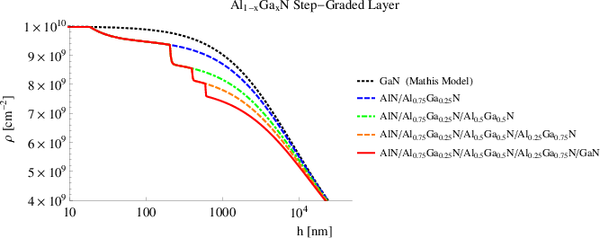
multilayer are considered. The first is a step-graded layer composed of Al0.75Ga0.25N
(200nm) / Al0.5Ga0.5N (200nm) / Al0.25Ga0.75N (200nm) / GaN. The results are
shown in Figure 5.18. The second structure is a (AlN/GaN)10 superlattice, and the
related evolution of the threading dislocation density is shown in Figure 5.19.
In both cases the initial and boundary conditions are the same as reported in
Paragraph 5.4.4.
Considering the red line in Figure 5.18, the threading dislocation density after four
interfaces at 1μm is 25% less than the initial value. A decrease of the threading dislocation
density of technological relevance should be at least of one order of magnitude. Therefore
this step graded layer seems to not be effective for improving the crystalline quality of the
device.
As can be observed in Figure 5.18, the threading dislocation density quickly decreases
suddenly after the critical thickness associated with each interface. This decrease is caused
by threading dislocation glide and is proportional to the lattice mismatch associated with
each interface.
The other curves of Figure 5.18 are related to multilayers with a lower number of
layers with respect to the one which is represented by the red line. The results
indicate that a lower number of layers decreases the threading dislocation density
less.
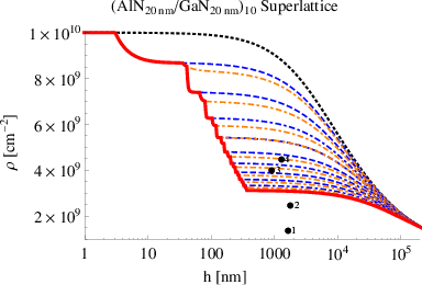
Figure 5.19 shows the development of threading dislocation density in a (AlN/GaN)10
superlattice. This is composed of 10 periods of AlN/GaN. Each layer is 20nm thick. The
superlattice is grown upon the AlN substrate and is h = 400nm high. A GaN layer extends
for h > 400nm.
The red line shows the threading dislocation density, calculated with the model of
Section 5.4, across the superlattice. Other lines show the threading dislocation
density with a lower number of layers in the superlattice. The black line corresponds
to the threading dislocation density according to Mathis [49] for a GaN layer
grown upon an AlN substrate. All curves have the same behavior at high thickness,
h > 105nm. However, differences among the cases are evident in the first 400nm.
In particular, the superlattice reduces the threading dislocation density by 70%
with respect to the initial value, resulting in a more efficient method than the
step-graded layer to decrease the dislocation density. Again, a lower number of layers
corresponds to a lower value of the final threading dislocation density. A quick decrease
of the threading dislocation density is visible after the critical thickness of each
interface is reached. This is caused by threading dislocation glide. However, the
density decreases more at interfaces placed at lower thicknesses than at higher
thicknesses. For example, the threading dislocation density decreases by 15% at
the first interface while it decreases by 1% at the last one. This is caused by the
incomplete relaxation of the misfit stress of each interface. The smaller the layer
thickness, the smaller the relaxation of the misfit stress. This implies that in the last
layers of a superlattice, the lattice parameter tends to be constant through the
thickness and equal to a value between the AlN and GaN lattice parameters. The
consequence it that a negligible lattice mismatch is present at high thicknesses, i.e.,
the misfit stress is small, i.e., the glide is negligible. Therefore, increasing the
number of layers after this threshold does not improve the crystalline quality.
One possible method to complete the stress relaxation is growth of a thick layer,
GaN or AlN, to recover the intrinsic value of the lattice parameter. Then a new
superlattice can be grown to further reduce the threading dislocation density. This
has been observed by several authors [14,85]. Their experimental data (points
3 and 4 in Figure 5.19) show a threading dislocation density which is slightly
smaller than the values predicted by the improved model because the experimental
structures are composed of several superlattices separated by thick layers. Other
experimental data [75,84] tend to confirm the prediction of the threading dislocation
density calculated according to the model proposed in this work (see Section 5.4).
 d
d
 d
d