|
|
|
|
Previous: 6.4 Using the Modified Energy Transport Model Up: 6. Modeling and Application Next: 6.6 Grid Matters |
|
|
|
|
Previous: 6.4 Using the Modified Energy Transport Model Up: 6. Modeling and Application Next: 6.6 Grid Matters |
The difference in the electron concentration is shown in Fig. 6.15. In the case of the standard energy transport model, the spreading of the hot electrons is much more pronounced than with the modified one.
![\includegraphics[width=.65\textwidth]{eps/2D_WellTemp_merged}](img1105.png) |
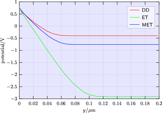
By looking at the potential in the device at a vertical cut located in the middle between source and drain (Fig. 6.16), the difference between the standard energy transport model and the modified one is also clearly visible. The standard energy transport model produces an anomalous decrease of the body potential.
 |
|
|
|
|
Previous: 6.4 Using the Modified Energy Transport Model Up: 6. Modeling and Application Next: 6.6 Grid Matters |