5.5.2 Hysteresis due to Stress
When  is lowered towards the stress voltage, as required in the OFIT
technique,
is lowered towards the stress voltage, as required in the OFIT
technique,  extracted from the rising and falling pulse edges start to deviate,
introducing a hysteresis. The hysteresis is only visible for larger pulse
amplitudes, indicating degradation (marked with
extracted from the rising and falling pulse edges start to deviate,
introducing a hysteresis. The hysteresis is only visible for larger pulse
amplitudes, indicating degradation (marked with  and
and  ) due to
stress. While the impact of the oxide traps visible during medium
) due to
stress. While the impact of the oxide traps visible during medium  appears to be fully recoverable, the component causing the hysteresis is not.
This can be seen in Fig. 5.13 and Fig. 5.14, where
appears to be fully recoverable, the component causing the hysteresis is not.
This can be seen in Fig. 5.13 and Fig. 5.14, where  increases during
subsequent measurements performed on the same device. We attribute this
hysteresis to the creation of additional interface states due to NBTI stress at
increases during
subsequent measurements performed on the same device. We attribute this
hysteresis to the creation of additional interface states due to NBTI stress at
 [78]. Starting at
  there is nearly no stress. The deeper
the device is stressed into inversion the larger the hysteresis becomes,
resulting in an increased offset for the next pulse. The total hysteresis
at a certain stress level hence not only consists of the hysteresis of the
momentary charge pumping measurement but depends on the previous
measurements .
there is nearly no stress. The deeper
the device is stressed into inversion the larger the hysteresis becomes,
resulting in an increased offset for the next pulse. The total hysteresis
at a certain stress level hence not only consists of the hysteresis of the
momentary charge pumping measurement but depends on the previous
measurements .
As displayed in the inset in Fig. 5.13, the very first pulses are almost free of
stress (no hysteresis,  ) and hence the deviation of
  from
from  is
entirely due to oxide traps. Only a negligible amount of interface states
is
entirely due to oxide traps. Only a negligible amount of interface states  are created by the measurement process. The hysteresis-free area will be
discussed in more detail in the next section.
are created by the measurement process. The hysteresis-free area will be
discussed in more detail in the next section.
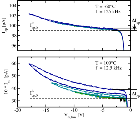
When the experiment is repeated at a lower frequency (see bottom of
Fig. 5.14), one finds that the interface state contribution can be scaled to the
reference frequency (
 ) [44]. This is compatible with the fact that
the stress duration is practically independent of frequency. On the other hand,
the recoverable oxide trap contribution to
) [44]. This is compatible with the fact that
the stress duration is practically independent of frequency. On the other hand,
the recoverable oxide trap contribution to  depends on frequency,
consistent with the idea that the lower the frequency (corresponding
to more time per pulse) the more oxide traps can contribute to
depends on frequency,
consistent with the idea that the lower the frequency (corresponding
to more time per pulse) the more oxide traps can contribute to  [95].
[95].
Finally, at a low temperature, displayed at the top of Fig. 5.14, practically
no hysteresis is introduced (no NBTI stress) and also the oxide trap
contribution is reduced, consistent with the idea that these traps are due to a
thermally activated tunneling mechanism [98] rather than elastic (and thus
temperature-independent) hole tunneling [94].
 can be identified for different frequencies
but equal temperature when checking against the left figure. Following these
results at least part of the defects must vary with temperature or frequency.
For better comparability, the data at
can be identified for different frequencies
but equal temperature when checking against the left figure. Following these
results at least part of the defects must vary with temperature or frequency.
For better comparability, the data at  are scaled to the reference
frequency (
are scaled to the reference
frequency ( ).
).