


Next: 4.3 Advanced Illumination Aperture
Up: 4.2 Lens Aberrations and
Previous: 4.2.3 Zernike Polynomials for
Spatial filtering at the lens pupil enhances the depth of focus while
maintaining high resolution capability in optical lithography.
From a physical point of view, in-lens filtering can be interpreted as an
amplitude superposition of plural images at different focal planes with
a controlled phase difference between them [21]. The technique
of multiple exposures at different focus levels was first introduced by
Hiroshi Fukuda et al. and is called FLEX [121,122].
It is closely related to the phase-shifting approach
(cf. Section 2.4.2), which realizes the phase-controlled amplitude
superposition in lateral direction instead of in axial direction
as with FLEX.
The operation principle can easily be demonstrated as follows: From
(4.51), (4.52) and
(4.69), (4.70) we obtain
for the coherent superposition of two focus levels
z = 

whereby the two contributions have the same amplitude Apq/2 but a phase
difference of 2 . Hence the composite spectrum equals
 |
(4.71) |
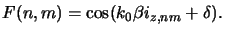
and the filter function F(n, m) is extracted to (cf. (4.69))
 |
(4.72) |
Alternatively, the cosine term (4.82)
can be added to the Fourier coefficients
Tnm of the mask [123], which is the principle of the
phase-shifting approach [16]. As can be seen from
(4.82)
the shape of the filter function F(n, m) depends on the distance 2 as well as the phase difference 2
 between the two planes.
Both parameters can easily be controlled and thus the filter
function can be optimized. For single features, e.g., a hole pattern,
a depth of focus three times larger with a 20% improved resolution
limit can be achieved,
whereas for a general VLSI pattern the depth of focus enhancement is
smaller but still ranges from 1.5-1.7 [21]. However,
this improvement comes at the expense of decreasing radial energy
concentration in the point spread function and decreasing overall energy
flux through the pupil [22].
The first limitation appears to be more serious,
since decreasing pupil transmission can, at least in principle, be compensated
for by increasing the source intensity. On the other hand, the loss of
energy in the central maximum in comparison to the secondary maxima results in
a loss of contrast in the image.
between the two planes.
Both parameters can easily be controlled and thus the filter
function can be optimized. For single features, e.g., a hole pattern,
a depth of focus three times larger with a 20% improved resolution
limit can be achieved,
whereas for a general VLSI pattern the depth of focus enhancement is
smaller but still ranges from 1.5-1.7 [21]. However,
this improvement comes at the expense of decreasing radial energy
concentration in the point spread function and decreasing overall energy
flux through the pupil [22].
The first limitation appears to be more serious,
since decreasing pupil transmission can, at least in principle, be compensated
for by increasing the source intensity. On the other hand, the loss of
energy in the central maximum in comparison to the secondary maxima results in
a loss of contrast in the image.
From a practical point of view, it is rather difficult to obtain
a continuous transmission distribution of a filter as given
in (4.82). Thus a simplified filter structure has to be
applied, which reduces the performance gain only slightly.
Additionally, the control of lens aberrations becomes very difficult
since the method modifies the core part of the lens. Finally, light reflection
and absorption in the filter are serious practical engineering problems
because the image quality is degraded by flare and the absorption causes
heat load problems.
Next: 4.3 Advanced Illumination Aperture
Up: 4.2 Lens Aberrations and
Previous: 4.2.3 Zernike Polynomials for
Heinrich Kirchauer, Institute for Microelectronics, TU Vienna
1998-04-17
![$\displaystyle \begin{aligned}U_i^{pq}(x,y) &= \frac{1}{2}\sum_{n,m} A_{pq} T_{n...
... e^{-j\delta}e^{-jk_0\beta i_{z,nm}}\right] e^{-j2\pi(nx/a+mq/b)},\end{aligned}$](img671.gif)