If multiple dopant streams are given, each stream represents a uncoupled PDE to solve. Because of the intrinsic doping conditions the diffusivities exhibit no concentration dependence.
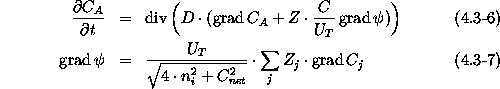
The coupled diffusion model accounts for the electric field of the charged dopants, (4.3-5) is extended by a field enhancement term, as shown in (4.3-6).
The electrostatic potential ![]() is calculated from the built-in potential
, hence, local charge neutrality and Boltzmann statistics
are assumed. Deriving the electrostatic potential leads to an explicit
formulation for the electric field (4.3-7). By substituting
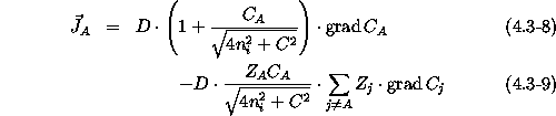
(4.3-7) into (4.3-6) the dopant diffusion flux becomes
is calculated from the built-in potential
, hence, local charge neutrality and Boltzmann statistics
are assumed. Deriving the electrostatic potential leads to an explicit
formulation for the electric field (4.3-7). By substituting
(4.3-7) into (4.3-6) the dopant diffusion flux becomes
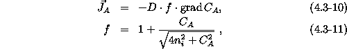
If only one dopant is present ( ![]() ) the diffusion flux
simplifies to
) the diffusion flux
simplifies to
where f is known as the field enhancement factor. This factor is close to
one for intrinsic conditions ![]() and two for high
concentrations
and two for high
concentrations ![]() .
.
In the case of multiple dopant diffusion (4.3-6) is set up for each
dopant. The resulting equations are representing a system of coupled PDEs,
where the coupling is established via the electrostatic potential and the
net doping, respectively. The impact of the field effect on the doping
profiles is demonstrated in the following example by a comparison between
the uncoupled and coupled diffusion model. The initial doping conditions are
selected for the sake of maximizing the field enhancement during diffusion
and would not be applied within a usual process technology. Two opposite
charged dopants, e.g. boron and arsenic, are in local vicinity under
extrinsic doping conditions. Figure 4.3-1 shows the result
obtained by the uncoupled diffusion model, but with dopant dependent
diffusivities. Therefore, the diffusion of arsenic is retarded in the
p-doped region and vice versa. A significant change in the dopant profiles
is given by using the coupled diffusion model (see Fig. 4.3-2). Due
to the strongly established electric field at the p-n junction the dopants
attract each other. A significant redistribution of the boron dopants
occured after 30min diffusion at ![]() , which cannot be explained by
normal diffusion behavior. The field enhancement is responsible for pushing
the boron concentration at the p-n junction above the initial implantation
value.
, which cannot be explained by
normal diffusion behavior. The field enhancement is responsible for pushing
the boron concentration at the p-n junction above the initial implantation
value.
From the computational point of view the coupled and uncoupled diffusion models are very efficient, because only the pure dopant streams are involved and the dopant-/point defect interactions are neglected. These models should be used as standard diffusion models for optimization purposes. The uncoupled diffusion model can be set up without loosing any accuracy for material regions where the dopants are uncharged, like silicon dioxide or nitride. If multiple dopants streams at extrinsic doping conditions are involved the coupled diffusion model is obligatory.