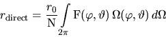
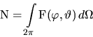
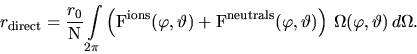
First of all, distribution functions means, that in the general case several species of particles with different distributions and integration limits will be present. Reactive ion etching, e.g., is determined by simultaneous impact of ionized and neutral particles. Moreover particles can have directly incident and reflected distributions originating from different directions. Generally speaking, the final equation for the rate will sum up different fractions with different integration domains.
Secondly, all considered surface positions means, that the surface of the structure has to be discretized. For the cellular geometry representation, the discretized surface is given by the list of material cells which are neighbored by vacuum cells. The accuracy of the volume discretization directly determines the resolution of the surface.
In order to detect the correct integration areas, finding the visible solid angle is a further prerequisite for the rate calculation. For this purpose, the upper hemisphere is scanned by rays starting at a considered surface position, which are tested for intersections with the geometry. For particles directly arriving from the sputter target scanning can be restricted to the upper hemisphere above the wafer. The rays are discretized by the voxels of the cellular representation. If a ray hits a material cell, direct particle incidence from this direction is screened.
![\begin{figure}\psfrag{dphi}[r][r]{$d\varphi$}
\psfrag{dtheta}[][]{$d\vartheta$}
...
...cludegraphics[width=0.5\textwidth]{eps-pvd/shadow.eps}}
\end{center}\end{figure}](img276.gif) |
For scanning the
hemisphere is divided into
![]() bins of size
bins of size
![]() (see Fig. 6.7), resulting in
(see Fig. 6.7), resulting in
![]() scanning operations for each of the approximately
scanning operations for each of the approximately ![]() surface
cells. This number can be reduced by following the limit between visible and
shadowed areas, instead of scanning the complete region. When propagating in
the polar scanning direction, the azimuthal angle has to be corrected by only a
few degrees and the number of operations for each surface cell is reduced from
surface
cells. This number can be reduced by following the limit between visible and
shadowed areas, instead of scanning the complete region. When propagating in
the polar scanning direction, the azimuthal angle has to be corrected by only a
few degrees and the number of operations for each surface cell is reduced from
![]() to approximately
to approximately
![]() , depending
on the step width chosen for
, depending
on the step width chosen for ![]() . The final result of visibility
testing is a discrete function
. The final result of visibility
testing is a discrete function
![]() which is either 1
for visible directions or 0 for shadowed ones.
which is either 1
for visible directions or 0 for shadowed ones.
Fig. 6.7 shows the polar plot of two common visibility functions. The dark
area delimited with the dashed line shows the opening of a circular via seen
from an off-center position at the bottom of the via. The light area within
the dashed-dotted line shows how a step is seen from a point located at a
certain distance away from its lower edge. The polar plot forms a hyperbola
reaching its limiting value
![]() for the two polar directions
parallel to the step. For the polar angles directed away from the step, where
the ray does not intersect with the geometry, the scanning operation is stopped
at the bounding box of the simulation domain.
for the two polar directions
parallel to the step. For the polar angles directed away from the step, where
the ray does not intersect with the geometry, the scanning operation is stopped
at the bounding box of the simulation domain.
With the visibility function
![]() the equation for the
calculation of the local rates
the equation for the
calculation of the local rates ![]() can be formulated as integral of the
distribution function
can be formulated as integral of the
distribution function
![]() and the visibility
function
and the visibility
function
![]() . First we only consider the contribution
from directly incident particles. Thus the integration can be limited to the
upper hemisphere and the formula results in
. First we only consider the contribution
from directly incident particles. Thus the integration can be limited to the
upper hemisphere and the formula results in
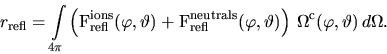
Reflections can only occur from the surface of the structure. Therefore the
``visibility'' function for reflected particles
![]() is the complement to the visibility function
is the complement to the visibility function
![]() . Reflections also occur from below, e.g., from the bottom of the
feature back to the sidewalls. Thus the rate contribution from reflected
particles with a separate treatment of ions and neutrals is
. Reflections also occur from below, e.g., from the bottom of the
feature back to the sidewalls. Thus the rate contribution from reflected
particles with a separate treatment of ions and neutrals is
Basically, reflection can be classified in four types. The simplest one is
diffuse reflection where the distribution of the reflected particles is
constant, cf. Fig. 6.8(a). For specular reflection from a certain
direction, the surface position, where the particle has been reflected has to
be traced back. After applying the reflection law which says that the angle of
reflectance is equal to the angle of incidence, cf. Fig. 6.8(b), the
reflected intensity from the considered direction is equal to the intensity
from the incident direction at the position where the reflection occurs.
Additionally, the reflected distribution can be approximated by an analytical
expression such as a cosine function, cf. Fig. 6.8(c). Finally, if the
reflection process is considered in his overall complexity, the reflected
distribution will be composed of specular and diffuse contributions,
cf. Fig. 6.8(d). In this case the reflected distribution has to be
calculated from the directly incident distribution by applying a transformation
Considering reflections means that only a fraction of the directly impinging
particles contributes to the rate equation. The sticking coefficient ![]() denotes the probability that a particle will stick at its initial incidence
position without being re-emitted and thus gives the fraction of effective
particles.
denotes the probability that a particle will stick at its initial incidence
position without being re-emitted and thus gives the fraction of effective
particles. ![]() gives the fraction of reflected particles.
Hence, the equation of the local rate
gives the fraction of reflected particles.
Hence, the equation of the local rate ![]() combines directly incident
(6.8) and reflected (6.9)
particles weighted by their fractions
combines directly incident
(6.8) and reflected (6.9)
particles weighted by their fractions
Beyond reflections a further interaction term has to be added when the process
is determined by angular dependent surface interactions, which is the case when
high energetic particles lead to a strongly physically based erosion of the
surface [28][82]. The intensity of the physical surface
interaction depends on the direction of the particle incidence with respect to
the surface normal and maximum interaction generally occurs for oblique
incidence directions. Therefore, yield functions typically show an angular
offset
![]() for the maximum
yield
for the maximum
yield
![]() with respect to the yield
with respect to the yield ![]() for
normal incidence, which can be approximated by a linear combination of cosine
functions of different orders [50] as shown in Fig. 6.9.
for
normal incidence, which can be approximated by a linear combination of cosine
functions of different orders [50] as shown in Fig. 6.9.
![\begin{figure}\psfrag{25 eV}{\framebox{25 eV}}\psfrag{100 eV}{\framebox{100 eV}}...
...cludegraphics[width=0.49\textwidth]{eps-pvd/100eV.eps}}
\end{center}\end{figure}](img294.gif) |
Most recently molecular-dynamics simulations of surface interactions
in metal film growth [23] have shown, that adsorption, reflection,
and etching processes are occurring simultaneously with different probabilities
depending on the angle of incidence. This effect can be taken into
consideration by an angular dependent sticking coefficient and by splitting up the distribution functions for the directly incident
particles into adsorbed/deposited and etching/reflected fractions which
contribute with different sign to the overall surface velocity
It is obvious that the final formula comprises many unknown parameters, like angular dependent particle distributions given separately for adsorption and etching as well as separately for each species, or at least for groups of particles with similar behavior. The list continues with reflection characteristics, the angular dependent sticking coefficients, and the parameters for the sputter yield functions and numerous more. Since many of these parameters are not accessible for measurements and experimental determination of the others is very time consuming, simplified fitting models have to be applied. Before introducing the different models for reactive ion etching, plasma and sputter deposition, the overall model for low-pressure processes will be concluded by the realization of the surface propagation
![]()
![]()
![]()
![]()
Prev: 6.1.3.2 Inclusion of Monte
Up: 6.1 Modeling of Low-Pressure
Next: 6.1.5 Surface Propagation
![\begin{figure}\psfrag{a}{(a)}\psfrag{b}{(b)}\psfrag{c}{(c)}\psfrag{d}{(d)}\psfra...
...twidth]{eps-pvd/reflection.eps}}
\par\vspace{-10mm}
\par\end{center}\end{figure}](img287.gif)
![\begin{figure}\psfrag{S}[][][1.2]{$\frac{\mathrm{S}(\alpha)}{\mathrm{S_0}}$}
\ps...
...ncludegraphics[width=0.6\textwidth]{eps-pvd/yield.eps}}
\end{center}\end{figure}](img289.gif)