
 |
|
||||
BiographyPaul Manstetten was born in 1984 in Berlin, Germany. He studied Mechatronics at the University of Applied Sciences Regensburg (Dipl.-Ing.) and Computational Engineering at the University of Erlangen-Nuremberg (MSc). After three years as an application engineer for optical simulations at OSRAM Opto Semiconductors in Regensburg he joined the Institute for Microelectronics in 2015 as a project assistant. He finished his PhD studies (Dr.techn.) in 2018 and works as a postdoctoral researcher on high performance methods for semiconductor process simulation. |
|||||
Ray Tracing in Non-Imaging Applications
Today, ray tracing is most commonly associated with computer graphics applications where the objective is to render an image from a virtual scene. Such a scene is typically a collection of objects represented mathematically. The image is generated by tracing rays originating from a viewport into the scene. The intersection of these original rays with the objects in the scene commonly generate subsequent rays to approximate the rendering equation, generating an equilibrium of the radiance in the scene. The radiance towards the viewport finally defines the values of the pixels in the rendered image.
Non-imaging applications that use ray tracing as a computational method can potentially profit from the algorithmic advances and optimized computational performance of ray-tracing engines developed for rendering applications in computer graphics. Ray tracing can for example be applied in the simulation of radiative heat transport, non-imaging optics and particle transport. In fact, for advanced semiconductor process simulations, the computational performance of a feature-scale etching or deposition process is largely determined by the ray-tracing performance.
The achievable ray-tracing performance is influenced by the underlying surface representation in an application and the pattern of rays requested by an application to be intersected with the surface. Fig. 1 illustrates different surface representations (i) using a signed-distance field, where the surface is implicitly represented by scalar values on a regular grid encoding the distance to the surface and using the sign to define inside and outside, (ii) using a set of overlapping spheres where the centers are located on the surface, (iii) using a set of overlapping oriented discs and (iv) using a closed triangle mesh representing the surface explicitly. Additionally, Fig. 1 schematically illustrates a coherent ray pattern originating from a single source and an incoherent pattern of rays originating from multiple source locations inside the domain.
Independent of the surface representation, an acceleration structure is required for a high throughput of intersection tests. Fig. 2 illustrates two types of acceleration structures, namely a bounding volume hierarchy and a tree-like subdivision of the domain together with examples of rays (red lines) and required intersection tests (green points). For the tree-like structure, a surface representation using a signed-distance field is indicated.
In practice, optimally utilizing ray-tracing algorithms and libraries from computer graphics in a non-imaging application requires a rigorous assessment of the requirements when it comes to the dynamics of the surface, surface representation, surface resolution, expected ray patterns, the underlying floating point data type of the calculations and targeted hardware platforms.
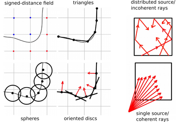
Fig. 1: Different surface representations and ray patterns.
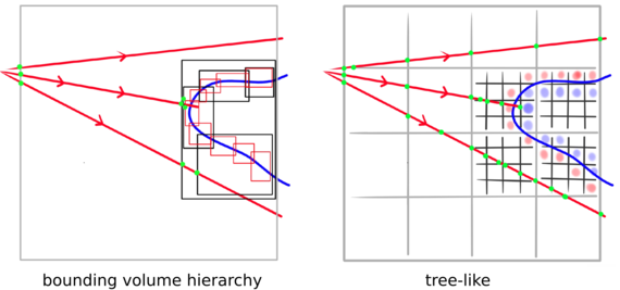
Fig. 2: Acceleration structures for ray intersection tests.