
 |
|
||||
BiographySimone Fiorentini was born 1992 in Verona, Italy. He received his Bachelor degree and Master Degree in Physiscs from the University of Padova, in 2014 and 2017, respectively. He carried out his Master Thesis at the Ruprecht-Karls University of Heidelberg through the Erasmus Program. After a short period working for an IT company in Milan, Italy, he joined the Institute for Microelectronics in November 2018, where he started his PhD studies. He is currently investigating ways to appropriately simulate both spin and magnetization dynamics in non-volatile magnetic memory devices. |
|||||
Coupled Spin and Charge Drift-Diffusion Approach Applied to Magnetic Tunnel Junctions
Non-volatility is an emerging solution to stand-by power leakages caused by the downscaling of traditional semiconductor components. Spin-transfer torque magnetoresistive random access memory (STT-MRAM) is a viable candidate thanks to its simple structure and compatibility with CMOS technology. It possesses both high speed and excellent endurance, as well as low fabrication costs. It is thus promising for applications ranging from IoT and automotive uses to embedded DRAM and last level caches.
Accurate simulations are a powerful tool in the design of STT-MRAM devices. The description of the temporal evolution of the magnetization, subject to spin-transfer torque, is given by solving the Landau-Lifshitz-Gilbert (LLG) equation. Modeling of STT switching can be performed by assuming a Slonczewski-like torque approach. This, however, allows one to approximately simulate the magnetization dynamics of the free layer only. A more complete description of the process can be obtained by computing the non-equilibrium spin accumulation across the whole structure. In a spin-valve with a non-magnetic spacer layer, this has been successfully accomplished by solving the spin and charge drift-diffusion equations. Modern STT-MRAM cells, however, employ a Magnetic Tunnel Junction (MTJ) for the memory bit.
We propose a method to apply these equations to an MTJ using a solver based on the Finite Element Method (FEM). The tunneling resistance defines the current through an MTJ, as it is much larger than the resistances of the ferromagnetic layers. For the non-uniform relative magnetizations which are characteristic to switching, the resistance and the current through an MTJ depend strongly on position. As Ohm’s law holds, we model the tunnel barrier as a (poor) conductor whose (large) resistivity depends on the relative orientation of the magnetization. The current can then be used to compute the spin accumulation and extract the torque acting on the magnetization.
We investigated the dependence of the torques on various parameters entering the spin accumulation equation, such as the diffusion coefficient of the ferromagnetic and non-magnetic layers, the length of the contacts of the structure, the exchange length and the usually neglected spin dephasing length. We also computed the dependence of the torques on the diffusion coefficient of the tunnel layer, which is a parameter we are free to choose in our formulation (Fig. 1). The torque acting on the magnetization, computed by choosing a set of realistic parameters for the non-magnetic and ferromagnetic layers and a high diffusion coefficient in the middle layer, is reported in Fig. 2. Such a torque is completely absorbed by the ferromagnetic layers, and its average value is comparable with the one predicted by Slonczewski. The solution for the spin accumulation, computed using our FEM solver with these parameters and a non-uniform magnetization configuration is reported in Fig. 3. The spin accumulation is redistributed in response to both the magnetization configuration and the current density distribution. This solution can be employed for computing the torques acting in the LLG equation at every time step.
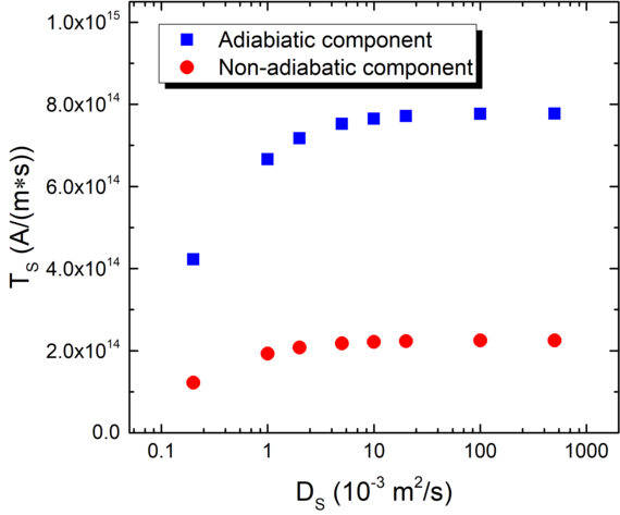
Fig. 1: Magnitude of the torque in the free layer as a function of the spin diffusion coefficient in the tunnel barrier. At high values of the coefficient, the torque does not depend on it.
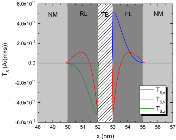
Fig. 2: Torque computed from the spin accumulation. NM is the non-magnetic contacts, RL is the reference layer, FL is the free layer and TB is the tunnel barrier. The magnetization in the reference layer is in the x-direction, and the one in the FL is in the z-direction. The average value of the torque is compatible with what is predicted by Slonczewski for an MTJ.
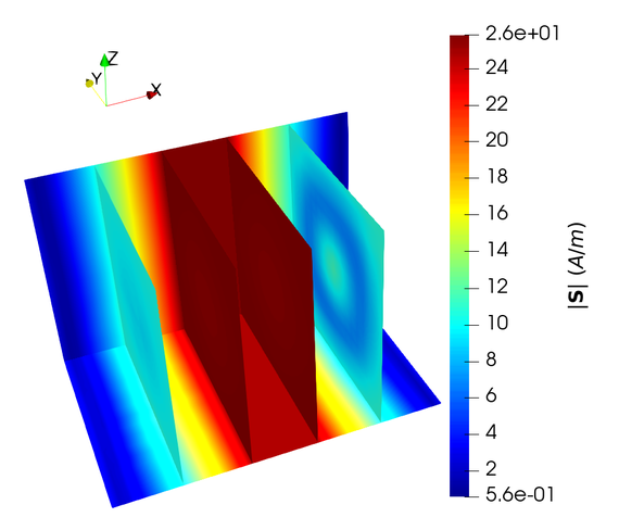
Fig. 3: Magnitude of the spin accumulation computed with a non-uniform magnetization configuration. The values are reported for 4 planes, located in the middle of the RL, at the left interface of the TB, at the right interface of the TB and in the middle of the FL, respectively.