Another very important effect occurring during device fabrication is
the phenomenon of segregation [13] [14]. The standard
treatment to simulate this effect is to split a simulation domain
into two different homogeneous regions separated by an abrupt
interface. The most common formulation to handle this problem is by
describing it as a segregation flux ![]() across the interface
across the interface
 |
(11) |
In some cases the separation into two different homogeneous regions is not treatable or leads to unacceptable errors. Therefore we tried to use the diffusion-segregation equation developed by Tan et al. [15] to solve a segregation effect with one single domain using a parameter dependent small transition zone to simulate the interface. The example can be described by the following equations
![$\displaystyle \frac{\partial C}{\partial t} = div\: \left[ D\: \left( grad\left( C\right) -\frac{C}{m}\: grad\left( m\right) \right) \right]$](img81.gif) |
(12) |
 |
(13) |
where
![]() is the species' solubility at an arbitrarily
chosen reference point 1.
is the species' solubility at an arbitrarily
chosen reference point 1.
Fig. 12 shows an in-diffusion-segregation profile of a species in a crystal consisting of three heterostructures where the first and the third area are of the same material. The conditions for the transmission zone at the interface are specified in a way so that the change of the materials takes place within one element. The smaller the element, the better are the numerical results in comparison to a sharp interface formulation.

|
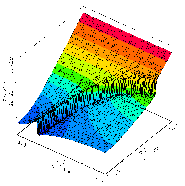
The two-dimensional simulation result (Fig. 13) shows the
advantage of an in-segregation model in case of non-planar geometries.
It is rather complicated with respect to the necessary meshing
algorithm to split this geometry into two separated regions whereas it
is comparable easy to solve the in-segregation along the given
interface. As boundary condition a Dirichlet boundary with a
concentration of
![]() has been chosen on the top
edge. All other boundaries are natural reflecting. The inhomogeneity
within the simulation domain is circular. The result shows that the
diffusing species are blocked at the boundary due to the material
interface. To increase the accuracy a grid criterion has been defined
which adapts the interface between the two materials. To minimize the
numerical error at the interface the same conditions for the
transition zone as in the one-dimensional case have been chosen.
has been chosen on the top
edge. All other boundaries are natural reflecting. The inhomogeneity
within the simulation domain is circular. The result shows that the
diffusing species are blocked at the boundary due to the material
interface. To increase the accuracy a grid criterion has been defined
which adapts the interface between the two materials. To minimize the
numerical error at the interface the same conditions for the
transition zone as in the one-dimensional case have been chosen.