|
|
|
|
Previous: 2.2.2 Operations on the Wafer Data Up: 2. Data Model Aspects for TCAD Simulators Next: 2.4 Classification of Process Steps |
|
|
|
|
Previous: 2.2.2 Operations on the Wafer Data Up: 2. Data Model Aspects for TCAD Simulators Next: 2.4 Classification of Process Steps |
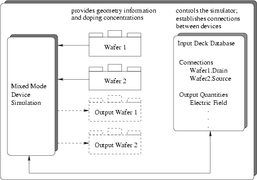
Additionally to the definition of the geometry, the grid information, and the quantities associated with a grid or a geometry, a simulator needs some more information which includes
An input deck database (IPD) that is capable of holding an arbitrary number of (simulator specific) parameters was developed at the Institute for Microelectronics [24,25]. The database provides a static object-oriented description language. It allows to group parameters into sections and inherit from one section into another. This inheritance mechanism is particularly useful in conjunction with a large number of parameters and to define hierarchical information. In this case default values for all parameters are supplied with the simulator in a defaults section. This section is inherited into a user definable section where only those parameters that need to be changed are listed.
This input deck database is also used to define circuitry information necessary to run mixed mode device simulations with the device simulator MMNT [26,27]. In the case of a mixed mode simulation several input Wafers are used. Connections between the Wafers (i.e. the circuitry information) are established by identifying the contacts of the devices. Fig. 2.4 depicts the data flow for the case of a mixed mode device simulation.
 |
2003-03-27