∕dy (for simplicity often called just the dislocation energy)
may be divided into two parts:
∕dy (for simplicity often called just the dislocation energy)
may be divided into two parts:
Dislocations are line imperfections in an otherwise perfect crystal. The atoms around a dislocation are displaced from their perfect lattice sites and the resulting distortion produces stress and strain fields around the dislocation line. Therefore, the dislocation is a source of internal stress in the crystal. The Burgers vector b represents the magnitude and the direction of the distortion in the crystal lattice. The stresses and the strains in the bulk of the crystal are sufficiently small to use the theory of linear elasticity to calculate them. This theory ceases to be valid around the dislocation line, where the stresses and the strains are infinite, and here non-linear theory should be applied. Consequently, it is necessary to exclude from the description a cylinder whose axis coincides with the dislocation line. The cylinder where linear elasticity breaks down is called core of the dislocation. The core is the plastic region of the system and the region around is the elastic one. The radius rc of the dislocation core is called inner cut-off radius and its order of magnitude is b. In this work, rc is taken to be b∕2 [19].
It is also necessary to limit externally the continuum under analysis with a second cylindrical surface having the dislocation line as the axis. The radius R of this second cylinder is called outer cut-off radius and its purpose is to keep expressions for the energy of the dislocation and the displacement field finite.
Linear elasticity is applied in the case of a straight infinite long dislocation to calculate its
energy and the related stress and strain fields, which will be used in the next chapters. The
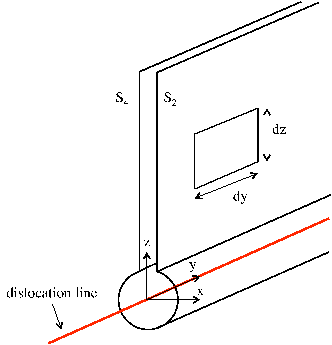
subsequent treatment is developed for the geometry shown in Figure. 3.1. The energy per
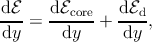
unit length of the dislocation d∕dy (for simplicity often called just the dislocation energy)
may be divided into two parts:
 | (3.1) |
where dcore∕dy and dd∕dy account for the energy inside and outside the dislocation core
region, respectively. For large film thickness h (see Figure. 3.1), the core energy constitutes
only a minor contribution to the total dislocation energy and is thus neglected in the
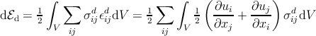
following calculation. Let σd be the stress tensor associated with the strain field εd
caused by the straight dislocation. Then the strain energy of the dislocation is given
by
 | (3.2) |
and using the symmetry of the stress tensor σijd = σ jid we get
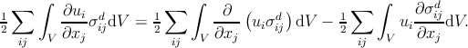 | (3.3) |
Recalling the equilibrium conditions for elastic media,
 | (3.4) |
one obtains
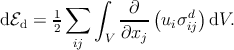 | (3.5) |
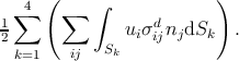
Using the Gauss-Ostrogradsky theorem to transform the volume integral into a surface integral over the surface S enclosing the volume V , we get:
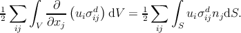 | (3.6) |
The surface S can be divided into four parts (see Figure. 3.1) and the last term can be rewritten as
 | (3.7) |
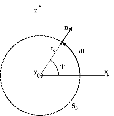
Since S1 is supposed to be infinitely far from the dislocation, the displacements vanish and the contribution of the surface is zero. The surface S3 is a cylindrical surface whose axis is aligned along the y-axis. Since the dislocation is infinite along the y direction, n = (nx, 0,nz):
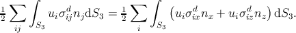 | (3.8) |
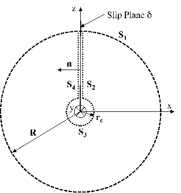
| Figure 3.1: | The dislocation is formed by an offset (defined by the Burgers vector b) of one side S4 of the slip plane δ with respect to the other side S2. The surface S3 encloses the dislocation core region. h denotes the film thickness. |
To simplify the integration, it is convenient to transform the Cartesian coordinates into cylindrical polar coordinates (see Figure 3.2) as
| x | = rc cos φ, | ||
| y | = t, | (3.9) | |
| z | = rc sin φ. |
 | (3.10) |
Considering that n =  , the dislocation energy expressed in (3.8)
becomes
, the dislocation energy expressed in (3.8)
becomes
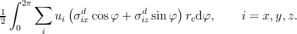 | (3.11) |
Expanding the last equation yields
 rc ∫
02π rc ∫
02π | 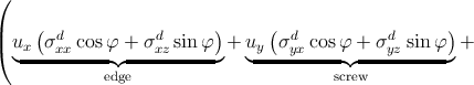 | ||
 dφ. dφ. | (3.12) |
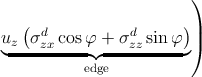
When the impact of the core integral along S3 is negligible, only the integrals along the surfaces S2 and S4 (see Figure. 3.1) have to be considered:
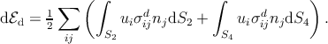 | (3.13) |
Considering Figure 4.2, dS2 = dS4 = dzdy the energy per unit length of dislocation is
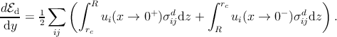 | (3.14) |
If the extremes of the second integral are inverted, one obtains
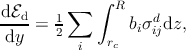 | (3.15) |
where ui(x → 0+) - u
i(x → 0-) = b
i.