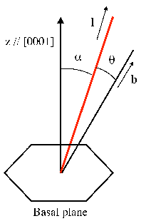
| Figure 3.7: | Dislocation geometry in a hexagonal crystal. |
The geometrical configuration of dislocations in real hexagonal single crystals depends on thermodynamic and kinetic factors. The theory described in the previous sections is used here to find the geometrical arrangement assumed by dislocations in the crystal structure in order to minimize their energy.
Sections 3.3 and 3.4 describe the procedures for the calculation of the dislocation energy in isotropic and hexagonal materials, respectively. This section shows the energetically most favorable configurations of dislocations in AlN, GaN and InN single crystals, using the above calculated pre-logarithmic coefficients (see Section 3.5). The dislocation disposition in three-dimensional space is given in terms of α and β, as shown in Figure 3.4. The dislocation arrangement is at first evaluated (Section 3.7.1) far from the free surface of the material and then (Section 3.7.2) close to it. The results are compared with those obtained within the isotropic approximation.
Assuming dislocations in the bulk means neglecting the effect of the material free surface. In
the bulk, dislocations are supposed to be inside an infinite medium, and the dislocation
energy per unit length of dislocation needs to be minimized in order to find the most
favorable configuration. d ∕dy calculated within the anisotropic approximation is directly
proportional to the pre-logarithmic coefficient K. As a consequence, the most
favorable configuration corresponds to the angles α and β which minimize K and
d∕dy.
∕dy calculated within the anisotropic approximation is directly
proportional to the pre-logarithmic coefficient K. As a consequence, the most
favorable configuration corresponds to the angles α and β which minimize K and
d∕dy.
Holec [25] has already shown that in an infinite isotropic continuum the dislocation energy is minimized when the dislocation line is aligned with the direction of the Burgers vector (see equation (3.16)). Therefore the screw-type dislocation always has the lowest energy within the isotropic approximation.
In order to understand how anisotropy affects the energetically most favorable dislocation
configuration, it is sufficient to evaluate the pre-logarithmic coefficient of Section 3.5. The
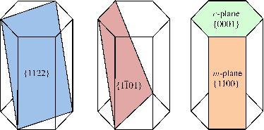
pre-logarithmic coefficient of the c-type dislocation (b = ![[0001]](DISS237x.png) ) as a function of the two
angles α and β is plotted in Figures 3.5, 3.5 and 3.5 for monocrystalline AlN, GaN and
InN, respectively. In all cases, the coefficient does not depend on the angle β because the
hexagonal c-plane is isotropic. Therefore all dislocation lines with different angles
β are equivalent. It follows that the lowest energy configuration is obtained for
α = 0∘ or α = 180∘. The Burgers vector b = 1∕3
) as a function of the two
angles α and β is plotted in Figures 3.5, 3.5 and 3.5 for monocrystalline AlN, GaN and
InN, respectively. In all cases, the coefficient does not depend on the angle β because the
hexagonal c-plane is isotropic. Therefore all dislocation lines with different angles
β are equivalent. It follows that the lowest energy configuration is obtained for
α = 0∘ or α = 180∘. The Burgers vector b = 1∕3![[0001 ]](DISS238x.png) is characterized by α = 0∘
and consequently its direction is coincident with the energetically most favorable
dislocation line. It follows that the c-dislocation is a screw-dislocation. The situation is
different for the a-type (b = 1∕3
is characterized by α = 0∘
and consequently its direction is coincident with the energetically most favorable
dislocation line. It follows that the c-dislocation is a screw-dislocation. The situation is
different for the a-type (b = 1∕3![¯
[2110 ]](DISS239x.png) ) and the (a + c)-type (b = 1∕3
) and the (a + c)-type (b = 1∕3![¯
[2113]](DISS240x.png) )
dislocations.
)
dislocations.
Directions of the a-type dislocations with the lowest K and energy have β = 180∘ and
α ≈ 130∘ for AlN, β = 0∘ or β = 180∘ and α ≈ 65∘ or α ≈ 115∘ for GaN (like [25]), β = 0∘
or β = 180∘ and α ≈ 70∘ or α ≈ 115∘ for InN. As the Burgers vector b = 1∕3![[¯2110]](DISS241x.png) is
characterized by β = 0∘ and α = 90∘, the Burgers vector and the dislocation line are
coplanar but not orthogonal nor coincident. Therefore, the energetically most favorable
configuration for the a-type dislocation is a mixed-type dislocation, unlike the screw-type
dislocation predicted by the isotropic approximation.
is
characterized by β = 0∘ and α = 90∘, the Burgers vector and the dislocation line are
coplanar but not orthogonal nor coincident. Therefore, the energetically most favorable
configuration for the a-type dislocation is a mixed-type dislocation, unlike the screw-type
dislocation predicted by the isotropic approximation.
Directions of the (a + c)-type dislocations with the lowest K and energy are β = 0∘ and
α = 0∘ or β = 180∘ and α = 180∘ for AlN, α = 0∘ or α = 180∘ for GaN (like [24]), and
α = 0∘ or α = 180∘ for InN. As the Burgers vector b = 1∕3![[¯2113]](DISS242x.png) is characterized by β = 0∘
and α ≈ 31.6∘, the Burgers vector and the dislocation line are coplanar but not orthogonal
nor coincident. Therefore, the energetically most favorable configuration for the a-type
dislocation is a mixed-type dislocation, which is again different from the prediction of the
isotropic theory.
is characterized by β = 0∘
and α ≈ 31.6∘, the Burgers vector and the dislocation line are coplanar but not orthogonal
nor coincident. Therefore, the energetically most favorable configuration for the a-type
dislocation is a mixed-type dislocation, which is again different from the prediction of the
isotropic theory.
In real finite crystals, dislocations which are not closed loops have to terminate at the free surface of the crystal and, consequently, they must have a finite length. Therefore, the energetically most favorable dislocation direction is not only a function of K but also of the actual length of the dislocation. As a consequence, during the growth of a monocrystalline layer over a surface where one dislocation terminates, the dislocation elongates following the shortest path to the new free surface. This is possible because the distance between the dislocation and the newly forming free surface is so small that it can not be neglected like it is assumed for dislocations in the bulk, which are far from the free surface.
In order to consider the effect of the free surface on the dislocation configuration, γ is defined as the angle between the dislocation line and direction orthogonal to the free surface. If the film thickness grows by Δh, then the dislocation length increases by Δh∕ cos α. The formulas for the dislocation energy that must be used within the isotropic and the anisotropic approximation are, respectively,
 = =   ln ln , , | (3.43) |
 = K = K ln ln . . | (3.44) |
The angle α associated to the lowest dislocation energy is calculated minimizing the expression (3.43) for the dislocation energy with respect to α. θ depends on the position of the Burgers vector of each kind of dislocation (see Figure 3.7). The results for the angle α are summarized in Table 3.3 for monocrystalline AlN, GaN and InN. Regarding GaN, the calculated angles match with the results of Mathis [49] and Holec [25].
| Table 3.3: | Angle α minimizing the dislocation energy for each kind of dislocation within isotropic elasticity. |
| b | AlN | GaN | InN |
| c | 0∘ | 0∘ | 0∘ |
| a | 0∘ | 0∘ | 0∘ |
| (a + c) | 14.5∘ | 14∘ | 10∘ |
The angle α associated to the lowest dislocation energy is calculated minimizing the expression (3.44) for the dislocation energy with respect to α. This has been done for (0001)-oriented monocrystalline AlN, GaN, and InN. Different crystallographic planes have been considered as free surface.
When the monocrystal is grown in the planar growth mode (Frank-van der Merwe growth), the free surface is the (0001) plane (the polar plane). In this case the angle α between the dislocation line and the [0001] direction, which minimizes the dislocation energy, is shown in Table 3.4. The calculation reveals that for the (0001) surface, dislocation lines along the [0001] direction constitute the lowest energy configuration for all three dislocation types (a-, (a + c)- and c-type) in AlN and GaN. This contradicts the results obtained within the isotropic approximation. Regarding InN, both a- and (a + c)-type dislocations are inclined with respect to the [0001] direction with different angles with respect to what is predicted with the isotropic approximation.
When the monocrystal is grown with the island growth mode (Volmer-Weber growth), the
free surface of an island can be the 1st order pyramidal plane (the  plane) or the 2nd
order pyramidal plane (the
plane) or the 2nd
order pyramidal plane (the  plane, also called the semipolar plane). For the first case,
the angle α minimizing d is shown in Table 3.5, while for the second case it is shown in
Table 3.6. Regarding GaN, the calculated angles matches with the results of Holec [25].
plane, also called the semipolar plane). For the first case,
the angle α minimizing d is shown in Table 3.5, while for the second case it is shown in
Table 3.6. Regarding GaN, the calculated angles matches with the results of Holec [25].
| Table 3.4: | Angle α minimizing the dislocation energy for each kind of dislocation in monocrystals (0001) oriented with (0001) free surface (planar growth mode). |
| b | AlN | GaN | InN |
| c | 0∘ | 0∘ | 0∘ |
| a | 0∘ | 0∘ | 69∘ |
| (a + c) | 0∘ | 0∘ | 24∘ |
| Table 3.5: | Angle α minimizing the dislocation energy for each kind of dislocation in
monocrystals (0001) oriented with  free surface (island growth mode). free surface (island growth mode). |
| b | AlN | GaN | InN |
| c | 0∘ | 24∘ | 0∘ |
| a | 0∘ | 65∘ | 67∘ |
| (a + c) | 0∘ | 35∘ | 0∘ |
| Table 3.6: | Angle α minimizing the dislocation energy for each kind of dislocation in
monocrystals (0001) oriented with  free surface (island growth mode). free surface (island growth mode). |
| b | AlN | GaN | InN |
| c | 0∘ | 23∘ | 0∘ |
| a | 0∘ | 64∘ | 67∘ |
| (a + c) | 0∘ | 34∘ | 0∘ |
Experimental TEM observations in III-nitrides regarding the dislocation inclination with respect to [0001], i.e., the angle α, are quite contradictory. Regarding GaN, Mathis [49] reports an inclination of 12∘, while Holec [25] suggests that dislocations are usually vertical rather than inclined straight lines. Other authors [22,42] mention an effective inclination of the dislocations with respect to [0001] direction without giving quantitative details.
It must be remarked that the inclination angles α here calculated are equilibrium values, i.e. they are obtained minimizing the dislocation energy. The real dislocation inclination could be affected by many kinetic factors, such as temperature and growth rate, which are not considered in this work.