=
=  ln
ln .
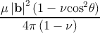
.Mathis [49] described the threading dislocation density in GaN bulk using a series of previous models developed by Romanov and co-workers in 1996 [64,65]. These models are based on reactions of inclined dislocations which change the threading dislocation density. The reactions among threading dislocations are caused by the minimization of the internal energy of the system. The energy per unit length of a dislocation with the Burgers vector b is within the isotropic approximation given by
| = ln. | (5.1) |
 = const ⋅ = const ⋅ 2. 2. | (5.2) |
 2 + 2 +  2 > 2 >  2(Frank′srule). 2(Frank′srule). | (5.3) |
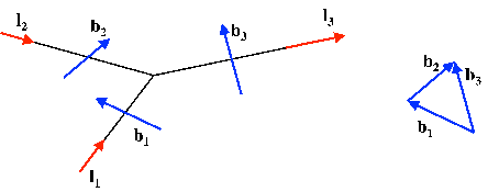
| Figure 5.1: | An example of a dislocation reaction (fusion) b1 + b2 → b3. Vectors b1, b2 and b3 are the respective dislocation line directions. |
Twenty different types of threading dislocations exist in a crystal with hexagonal symmetry (see Figure 5.2): two different types of screw dislocations with b = ±c, six different types of edge dislocations with the Burgers vectors b = ±ai (i = 1, 2, 3), and 12 different mixed threading dislocations with b = ±c ± ai (i = 1, 2, 3). Table 5.2 shows the products of reaction among these threading dislocations according to Frank’s rule.
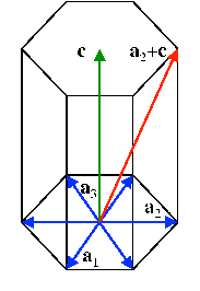
| Figure 5.2: | Hexagonal lattice. Burgers vectors of the type 1∕3⟨110⟩ are blue. Burgers vector of the type ⟨0001⟩ is green. Burgers vector of the type 1∕3⟨113⟩ is red. |
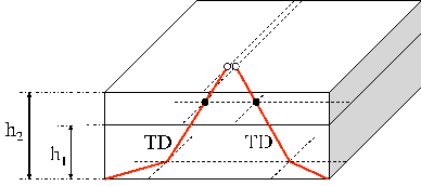
In Romanov’s [64,65] and Mathis’ [49] models, threading dislocations do not move physically (i.e. do not glide or climb), instead movements result from growth. Suppose the situation sketched in Figure 5.3.
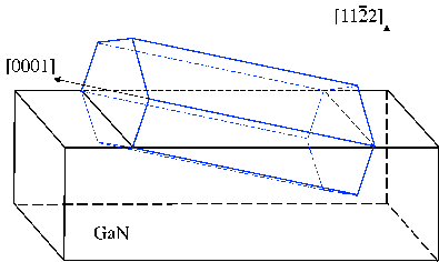
The threading dislocation segments are inclined with respect to the growth direction and as a consequence the terminating points at the upper surface move laterally and can eventually come in contact with each other. The threading dislocation intersections with the free surface will move until the point where they come within a distance r such that the interaction forces are sufficient to initiate an additional motion of dislocations. At this point they start to react among each other. The growth surface is assumed to be planar, which corresponds to a Frank-van der Merwe’s layer-by-layer growth mode. Mathis considered threading dislocations in bulk GaN, supposing the dislocations are lying on planes which are inclined with respect to the [0001] growth direction and thus during the growth may become close enough to react. The inclination of (some) dislocations was obtained by considering the dislocation energy within the isotropic theory. In Chapter 3, the optimal dislocation line direction for c- and a-type dislocations in elastically isotropic GaN is vertical whereas for (a + c)-type dislocations it is approximately 14.5∘ inclined from the vertical direction, which is similar to Mathis’ result of 15.6∘. Mathis also presented TEM evidence for some dislocations being inclined and claimed agreement with the above mentioned inclination angle. Section 3 shows that within the anisotropic theory all dislocations are parallel to the [0001] direction. In an absence of factors which can incline the dislocations, such as the island growth mode or impurities, the vertical threading dislocations are not able to come close enough to react, so the model can not be applied. A simple application of Mathis’ model is given in the next Paragraph, where the threading dislocation density is calculated in a GaN film and where the growth direction is the [112] direction (see Figure 5.4). In this situation, Mathis’ treatment is used to calculate the threading dislocation density because all threading dislocation types are inclined with respect to the [112] direction, as shown in Table 3.6. The discussion of the results will provide a first general idea about which model parameters affect the threading dislocation density more.
| Table 5.1: | Reaction table [49] for threading dislocations (TDs) in GaN with hexagonal symmetry. Reactions which are not possible either due to the Frank’s criterion or for geometric reasons are indicated with a “—” while reactions which are possible are indicated with their designated number. Reactions producing two dislocations are denoted with two numbers corresponding to their products. Annihilation reactions are denoted by “A”. |
|
| 1 | 2 | 3 | 4 | 5 | 6 | 7 | 8 | 9 | 10 | 11 | 12 | 13 | 14 | 15 | 16 | 17 | 18 | 19 | 20 |
|
|
| a1 | -a1 | a2 | -a2 | a3 | -a3 |
|
|
|
|
|
|
|
|
|
|
|
| c | -c |
|
|
|
|
|
|
|
|
|
|
| |||||||||||||
| 1 | a 1 | – | — | — | — | — | — | — | — | 19 | 20 | 17 | 18 | — | — | 13 | 14 | — | — | — | — |
| 2 | -a 1 | — | — | — | — | — | — | 19 | 20 | — | — | — | — | 15 | 16 | — | — | 11 | 12 | — | — |
| 3 | a 2 | — | — | — | — | — | — | 17 | 18 | — | — | — | — | 19 | 20 | 9 | 10 | — | — | — | — |
| 4 | -a 2 | — | — | — | — | — | — | — | — | 15 | 16 | 19 | 20 | — | — | — | — | 7 | 8 | — | — |
| 5 | a 3 | — | — | — | — | — | — | 13 | 14 | — | — | 9 | 10 | — | — | — | — | 19 | 20 | — | — |
| 6 | -a 3 | — | — | — | — | — | — | — | — | 11 | 12 | — | — | 7 | 8 | 19 | 20 | — | — | — | — |
| 7 | a 1+c | — | 19 | 17 | — | 13 | — | — | 1&1 | — | A | — | 6 | — | 1&4 | — | 4 | — | 1&6 | — | — |
| 8 | a 1-c | — | 20 | 18 | — | 14 | — | 1&1 | — | A | — | 6 | — | 1&4 | — | 4 | — | 1&6 | — | 1 | — |
| 9 | -a1+c | 19 | — | — | 15 | — | 11 | — | A | — | 2&2 | — | 2&3 | — | 5 | — | 2&5 | — | 3 | — | 2 |
| 10 | -a1-c | 20 | — | — | 16 | — | 12 | A | — | 2&2 | — | 2&3 | — | 5 | — | 2&5 | — | 3 | — | 2 | — |
| 11 | a2+c | 17 | — | — | 19 | 9 | — | — | 6 | — | 2&3 | — | 3&3 | — | A | — | 2 | — | 3&6 | — | 3 |
| 12 | a2-c | 18 | — | — | 20 | 10 | — | 6 | — | 2&3 | — | 3&3 | — | A | — | 2 | — | 3&6 | — | 3 | — |
| 13 | -a2+c | — | 15 | 19 | — | — | 7 | — | 1&4 | — | 5 | — | A | — | 4&4 | — | 4&5 | — | 1 | — | 4 |
| 14 | -a2-c | — | 16 | 20 | — | — | 8 | 1&4 | — | 5 | — | A | — | 4&4 | — | 4&5 | — | 1 | — | 4 | — |
| 15 | a3+c | 13 | — | 9 | — | — | 19 | — | 4 | — | 2&5 | — | 2 | — | 4&5 | — | 5&5 | — | A | — | 5 |
| 16 | a3-c | 14 | — | 10 | — | — | 20 | 4 | — | 2&5 | — | 2 | — | 4&5 | — | 5&5 | — | A | — | 5 | — |
| 17 | -a3+c | — | 11 | — | 7 | 19 | — | — | 1&6 | — | 3 | — | 3&6 | — | 1 | — | A | — | 6&6 | — | 6 |
| 18 | -a3-c | — | 12 | — | 8 | 20 | — | 1&6 | — | 3 | — | 3&6 | — | 1 | — | A | — | 6&6 | — | 6 | — |
| 19 | c | — | — | — | — | — | — | — | 1 | — | 2 | — | 3 | — | 4 | — | 5 | — | 6 | — | — |
| 20 | -c | — | — | — | — | — | — | 1 | — | 2 | — | 3 | — | 4 | — | 5 | — | 6 | — | — | — |
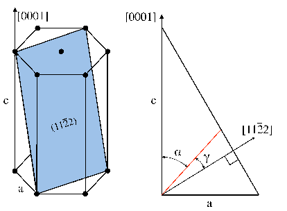
Chapter 3 shows that in GaN all dislocations close to the (112) facet are inclined with respect to the [0001] direction. The related angles α of inclination are listed in Table 3.6. Mathis’ model is used to calculate the threading dislocation density in semipolar GaN since all dislocations are inclined with respect to the [112] growth direction. The inclination angle with respect to the [112] direction is denoted γ in Figures 5.5.
The angle γ for the three threading dislocation types are calculated using the inclination angle θ listed in Table 5.2 and the GaN lattice parameters a and c.
| Table 5.2: | Inclination angle γ of threading dislocations (TDs) with respect to the [112] direction. |
| TD type | α | γ |
| c | 23∘ | 35∘ |
| a | 64∘ | 6∘ |
| (a + c) | 34∘ | 24∘ |
Using these values within Mathis’ model allows for the calculation of the threading dislocation density in semipolar GaN. The equations of Mathis’ model are solved supposing that all types of dislocations can react with each other and be produced by reactions between other dislocation pairs. Eight different initial conditions are defined changing the proportion among the dislocation families (see Table 5.3).
| Table 5.3: | Ratios of the three threading dislocation (TD) types (in %) used as initial conditions. |
| c-type TD | a-type TD | (a+c)-type TD | |
| 1 | 0 | 70 | 30 |
| 2 | 0 | 30 | 70 |
| 3 | 10 | 70 | 20 |
| 4 | 10 | 20 | 70 |
| 5 | 20 | 70 | 10 |
| 6 | 20 | 10 | 70 |
| 7 | 30 | 70 | 0 |
| 8 | 30 | 0 | 70 |
The interaction radius is set to 40 nm [79]. The initial value for threading dislocation density is set to 1010cm-2, which is a typical value for III-nitride grown upon non native substrates [38,56,81].
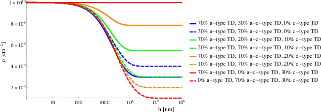
| Figure 5.6: | The total threading dislocation density, called ρ, as a function of the GaN thickness h for different initial conditions. |
Figure 5.6 shows the total threading dislocation density (i.e., the sum of the densities of the twenty dislocation families) as a function of the film thickness for the different initial conditions listed in Table 5.3. For all cases, the general behavior can be divided into three stages. The first stage covers the initial 100nm of the film thickness, where the density is almost constant, i.e., the number of occurring reactions is small because the inclination angle is small. In the second stage, between 100nm and 10μm, the density decreases from the initial value until a saturation point. The reduction is caused by reactions among dislocations. After 10μm, the density becomes constant, meaning that reactions are no longer taking place. The saturation of the threading dislocation density was observed experimentally by several authors [3,34,47]. Consider now the different curves of Figure 5.6. Keeping constant the starting value of c-type threading dislocations, an initial amount of (a + c)-type threading dislocations, which is bigger than a-type threading dislocations, implies a lower final asymptotical value of the density. This is explained by the fact that (a + c)-type threading dislocations have an inclination angle γ bigger than the corresponding one for a-type threading dislocations. Despite the influence of the inclination angle, it is not always straightforward to predict the results only based on considerations of the inclination angle.
For example, increasing the initial amount of c-type threading dislocations when the initial amount of a-type threading dislocations is bigger than the initial amount of (a + c)-type threading dislocations, causes the final threading dislocation density to increase. This is explained considering the particular case where there are no initial (a + c)-type threading dislocations (see the red solid line in Figure 5.6). Here, the threading dislocation density does not change from the initial value because no reactions can take place among a-type threading dislocations themselves, among c-type threading dislocations themselves, and between a-type threading dislocations and c-type threading dislocations, as shown by Table 5.2. Instead, increasing the initial amount of c-type threading dislocations when the initial amount of a-type threading dislocations is lower than the initial amount of (a + c)-type threading dislocations, causes the final value of threading dislocation density to decrease. In all cases, after 10μm, the overall decrease from the initial density is less than one order of magnitude, independently of the initial conditions. This decrease is not enough to improve the performance of real devices. Therefore, a better method to reduce the threading dislocation density is the use of multilayered structures. In this situation, Mathis’ model [49] is no longer sufficient to calculate the threading dislocation density due to the presence of interfaces among lattice-mismatched films. Under such circumstances, a threading dislocation glide along the interface must be considered as an additional source of reactions. In the next Paragraph, a threading dislocation glide along the interface is evaluated together with the evolution of the misfit dislocation density. The model of misfit dislocation density will be incorporated into an improved treatment capable of evaluating the threading dislocation density in heterostructures (see Section 5.4).