6.1 Electrostatic lenses
6.1.1 Introduction
An electrostatic lens refers to a specially shaped potential with convex/concave features, similar to optical lenses, used to steer coherent electrons. The concept was
first demonstrated experimentally in 1990 in [152, 153], in low-temperature, high-mobility semiconductors, which ensured that the coherent electrons had a
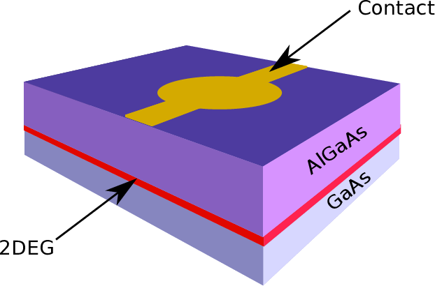
sufficiently long mean free path to conduct experiments with structures made with the lithographic capabilities at that time. An experimental realization of the
electrostatic lenses is illustrated in Figure 6.1.
The astounding decrease of the feature sizes in semiconductor devices, along with novel materials like graphene, has made (semi-)ballistic electron transport
applicable at room temperature [154]. This has sparked new interest in applying electrostatic lenses in nanoelectronic devices, e.g. [155] suggests the use of lenses to
focus electrons to the centre of nanowires, thereby avoiding rough interfaces and increasing mobility.
6.1.2 Law of refraction
Electrostatic lenses use analogous concepts from geometrical optics: Snell’s law describes the refraction of a light beam traversing an interface between two different
media of propagation, e.g. air and glass. An equivalent law of refraction can be derived for electrostatic lenses using the principle of energy
conservation.
A particle with a wavevector k has a kinetic energy
where ℏ denotes the reduced Planck constant and m* the effective mass. As a particle traverses the interface between regions at different potentials (illustrated in
Figure 6.2), its kinetic and potential energies change. The change in kinetic energy is attributed only to the change of the component of the wavevector normal to the
interface (red); the component parallel to the interface (blue) is left unchanged. It follows that
where θ1  is the angle of incidence (refraction) with respect to the normal of the interface. The magnitude of the wavevector is proportional to the square root of
the kinetic energy:
Therefore, the square root of the kinetic energy of a particle is analogous to the refractive index used in geometrical optics and this value can be
dynamically modified by changing the value of the potential energy in the region of the lens. This concept is illustrated in the following section.
is the angle of incidence (refraction) with respect to the normal of the interface. The magnitude of the wavevector is proportional to the square root of
the kinetic energy:
Therefore, the square root of the kinetic energy of a particle is analogous to the refractive index used in geometrical optics and this value can be
dynamically modified by changing the value of the potential energy in the region of the lens. This concept is illustrated in the following section.
6.1.3 Converging lens
Optical lenses which operate in a medium (air) with a lower refractive index use the familiar double-convex shape to focus light. Rays are refracted towards the
normal of the interface as they enter the lens. The law of refraction for electrostatic lenses (6.2) reveals that if a positive potential step is used for the lens, the kinetic
energy (refractive index) decreases and the trajectory of the electron is bent away from the normal to the interface. This dictates that a double-concave shape is
needed to form a converging lens with a positive potential [153]. Conversely, a negative potential, i.e. a well, would require a double-concave
shape.
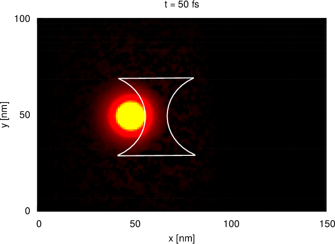
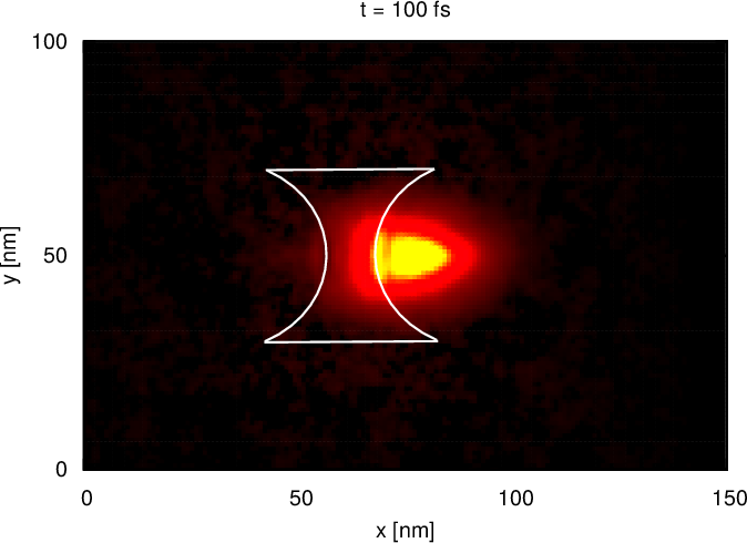
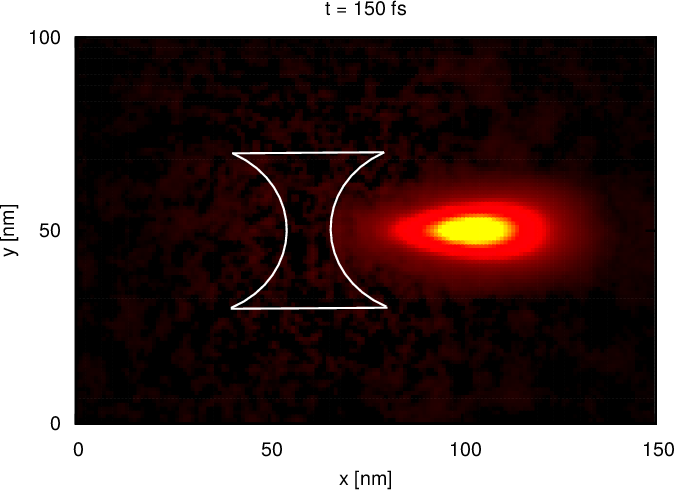
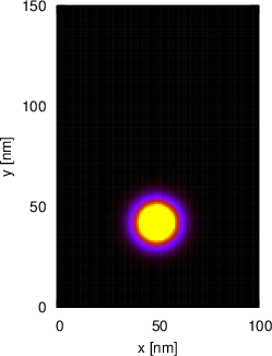
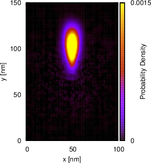
The potential shape used to form the electrostatic lens is shown in Figure 6.3. The electrostatic lens has a peak potential energy of 40meV and the wavepacket is
initialized with a kinetic energy of 180meV, moving rightwards. The electrostatic lens clearly focuses the wavepacket (density) after 150fs of evolution. A comparison
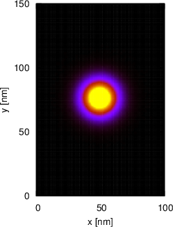
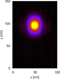
to the evolution without a lens is shown in Figure 6.4, using a similar setup in the vertical orientation. A further consideration for designing the lens is that the size
of the lens should be larger than the De Broglie wavelength of the electron (determined by its energy), otherwise an effective focusing will be distorted by diffraction
effects.
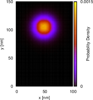
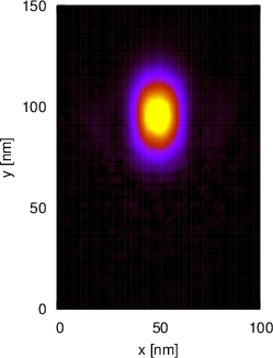
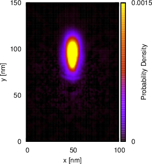
The refractive index of the lens, and thereby its focal length, can be modified by varying the magnitude of the potential with which it is formed; a larger value of the
potential energy for the lens (relative to its surrounding region) invokes a stronger refraction (’bending’). Figure 6.5 compares the effect of different values: It can
be clearly seen that the barrier with the higher potential energy focuses the wavepacket more sharply (at the distance observed at the time
instance shown). The applied potential can thereby control, when and at which distance, a wavepacket is focused (on a detector, for instance).
6.1.4 Wavepacket control
The converging lens demonstrated in the preceding section, follows from classical analogues in geometrical optics. It is possible, however, to extend
the concept of electrostatic lenses much further: engineered potential profiles can be used to dynamically control wavepackets, e.g. creating
entangled states by splitting up wavepackets. It should be noted that the electron is not physically split; it is a single electron in an entangled
state.
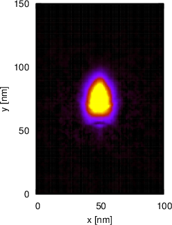
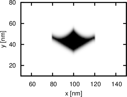
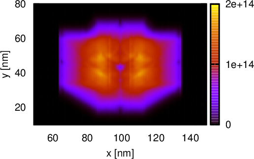
Figure 6.6 shows a rhomboid-like potential shape, along with the corresponding generation rate, which forms a lens that is able to realize such a function. The
behaviour of the lens can be manipulated by changing the magnitude of the potential. This can be done dynamically, if the lens is realized with a structure similar to
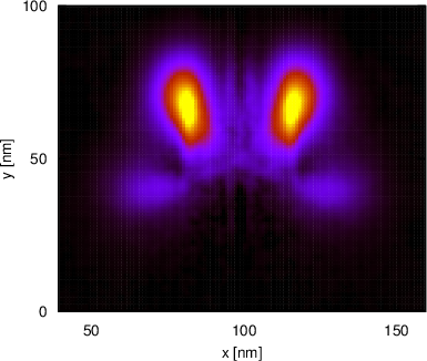
the one shown in Figure 6.1, using a time-dependent potential bias on the contact. Figure 6.7 illustrates the effect of the lens at different potential values. The
density peaks indicate regions with a higher probability to find an electron. In Figure 6.7b (peak potential energy 70meV) the wavepacket almost
fully traverses the lens and is split into two parts. The same lens shape, but with a potential energy of 120meV, splits the wavepacket into
four parts (Figure. 6.7b): The front edges splits off a portion of the wavepacket by reflection, while the concave-shaped rear edges focus the
transmitted parts again (applying the principle of Section 6.1.3). In the first case, with two peaks (the most-probable components of the state), the
y-component of the wavevector remains positive, whereas for the second case, at a higher potential energy, the wavevector of the scattered state also
has a negative y-component. This example clearly illustrates how specially shaped potentials can be used to influence the scattering pattern
of an electron wavepacket. By varying the potential energy the electron can be guided in a certain direction with a controllable probability.
This can be of use in the field of quantum computing to generate a (modifiable) entangled state and direct it to other computing elements.