We assume that the virgin devices may be considered as symmetrical. For
those devices  holds. From the experimental
 data the trap density
  at
at  can be calculated by
This relationship is derived in Appendix G. The factor
 can be obtained by a steady-state numerical
calculation. Neglecting the second term in the brackets, which represents
a correction due to the
can be obtained by a steady-state numerical
calculation. Neglecting the second term in the brackets, which represents
a correction due to the  effect,
expression 3.130 reduces to the one usually applied in
literature [423][272][271]
effect,
expression 3.130 reduces to the one usually applied in
literature [423][272][271]
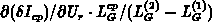
The second term in the brackets in 3.130 can be approximated
with the corresponding value in the channel. We further assume that the traps
are uniformly distributed in the channel. Note that the trap density can vary
in the source and drain junctions due to high dopant concentration or as a
result of technological process. Three approaches to evaluate this parasitic
term are presented in Appendix G. In the first method, the
charge-pumping current  is calculated by the transient numerical
simulation assuming traps in the middle of the channel. In this case,
only varies with
is calculated by the transient numerical
simulation assuming traps in the middle of the channel. In this case,
only varies with  because of the effect. In the second
approach we calculate the dependence of the threshold voltage
because of the effect. In the second
approach we calculate the dependence of the threshold voltage  on
by using the steady-state numerical simulation and approximate
on
by using the steady-state numerical simulation and approximate
 . In the third method, is calculated for two
equivalent devices with different gate lengths (
. In the third method, is calculated for two
equivalent devices with different gate lengths ( and
and  ).
These devices can represent two devices laying close to each other on the same
wafer. The difference between in these two devices
).
These devices can represent two devices laying close to each other on the same
wafer. The difference between in these two devices  may
be directly used to estimate the second parasitic term in
relationship 3.130 by
may
be directly used to estimate the second parasitic term in
relationship 3.130 by
 ,
where
,
where  is the effective channel length
of the device considered for formula 3.130. This approach
is equivalent to the first method, but it can be probably exploited in
measurements. For this method to yield proper results in practice, the trap
density distribution must be very close in both devices. Experimental work is
necessary here.
is the effective channel length
of the device considered for formula 3.130. This approach
is equivalent to the first method, but it can be probably exploited in
measurements. For this method to yield proper results in practice, the trap
density distribution must be very close in both devices. Experimental work is
necessary here.
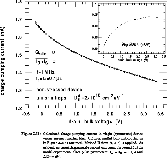
In the following we evaluate expressions 3.130
and 3.131. The first example is shown in
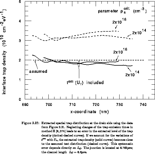
Figures 3.31 and 3.32. The dashed
curve in Figure 3.32 is the assumed uniform trap
distribution in the channel and both junctions in a virgin device. For this
uniform distribution the charge-pumping characteristic is
calculated numerically, Figure 3.31. Note that the drain
and source are connected together. The trap distributions obtained by applying
formulas 3.130 and 3.131 on the
calculated data are shown in Figure 3.32
for the different parameter  . Neglecting the second term due to
the effect yields an overestimation of the exact (assumed)
distribution (dotted-dashed curves). Accounting for the variable
. Neglecting the second term due to
the effect yields an overestimation of the exact (assumed)
distribution (dotted-dashed curves). Accounting for the variable  the
recalculated curves become close to the assumed distribution (solid lines),
giving a confirmation for formula 3.130. Note that the
error due to neglecting the parasitic term increases with increasing channel
length (in this example the gate length is
the
recalculated curves become close to the assumed distribution (solid lines),
giving a confirmation for formula 3.130. Note that the
error due to neglecting the parasitic term increases with increasing channel
length (in this example the gate length is  ).
).
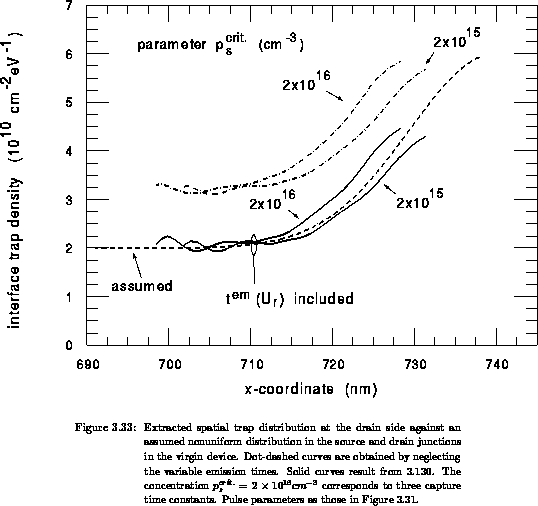
The second example is given in Figure 3.33. The dashed
curve is an assumed nonuniform trap distribution within the drain junction
in virgin device. We assume that the symmetrical trap distribution is at
the source side, as well. Note that a lateral trap nonuniformity near and
within the junctions can result from the technological process due to
implantation damage or the presence of high dopant concentration near the
interface [441]. For the assumed trap distribution, the is
calculated numerically. In accounting for the variable the recalculated
curve (solid lines) becomes close to the assumed nonuniform distribution, while
neglecting this effect leads to a systematic overestimation of the extracted
trap density (dotted-dashed curves). Note that in this example the critical
concentration  corresponds to three capture
time constants (expression 3.128).
corresponds to three capture
time constants (expression 3.128).