 |
A master-slave strategy is implemented, where the master process provides all the I/O operations and controls and synchronizes the behavior of all slaves which perform the trajectory calculations.
The most obvious parallelization strategy would be to successively distribute the trajectory calculation among the available slaves. But such a simple method has two significant drawbacks. First the damage accumulation is not considered correctly, because if the trajectories are arbitrarily distributed among the slaves the order of trajectory calculation is non-deterministic, which results in spatially varying damage accumulation. This effect is negligible as long as the number of slaves is significantly less then the number of ions. The number of ions simulated is in the range of some hundreds of thousands for two-dimensional applications and some tenth of millions for three-dimensional applications, while the number of workstations is typically of the order of ten. The more severe problem is that an arbitrary distribution of the trajectory calculation requires a continuous exchange of simulation results between the slaves, in order to correctly handle the influence of the damage on the ion trajectories. The histograms where the simulation results are stored had to be updated regularly. Even if very smart update methods are used this requires a data transfer of at least several MB in case of a three-dimensional simulation. This transfer would only be acceptable for massively parallel computers but not for a cluster of workstations usually connected by fairly slow 10 MBit/s or 100 MBit/s networks.
In the actual Parallelization method a transient simulation is explicitly introduced as already mentioned in Sec. 4.3. The simulation time is divided into several time steps, and it is assumed that ions belonging to the same time step do not influence each other. This requirement is met if the distance between the entrance points is larger than the lateral range of the ions or if the number of ions per time step is small compared to the total number of simulated ions, which guarantees an almost constant damage within a time step. Both requirements are met because on one hand side the ions are started from within sub-windows (Sec. 4.3) with a size of the order of the lateral range of the ion. Therefore the average distance between two ions is larger than the vertical range, which is normally smaller than the lateral range. On the other hand side the number of ions simulated during one time step is less than 0.1 % of the total number of simulated ions, because for typical three-dimensional applications the number of sub-windows is of the order of 1000 and for two-dimensional applications it is of the order of 50, which is small compared to some million or some ten thousands of simulated ions.
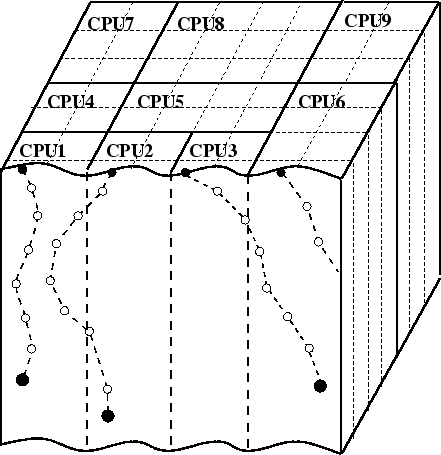
To distribute the trajectory calculation among several slaves the simulation domain is divided into prismatic subdomains with a square base with a size slightly larger than the lateral range of the implanted ions. The subdomains are aligned to the z-axis of the simulation domain and correlated to the histograms where the simulation data are stored to get an exact assignment between the data memory and the subdomains. Each slave is responsible for several of these subdomains as illustrated in Fig. 4.22 and therefore for a certain part of the simulation domain and the simulation memory. This means that each slave calculates all parts of particle trajectories and stores all simulation results within its scope of responsibility, while a particle is transfered to an other slave if the particle leaves the scope of responsibility. Thereby the communication between the slaves can be minimized as well as the memory requirement of the slave, because only a part of the complete simulation results has to be stored locally. Communication only occurs if a particle leaves the scope of responsibility of a slave or if it moves in the vicinity of the border of the scope of responsibility. If the number of available slaves (processors) is very high, each slave is just responsible for one subdomain. Therefore the number of usable processors is limited.
 |
![]()
![]()
![]()
![]() Previous: 4.6.3 Parallelization Method
Up: 4.6.3 Parallelization Method
Next: 4.6.3.2 Optimized Distribution Scheme
Previous: 4.6.3 Parallelization Method
Up: 4.6.3 Parallelization Method
Next: 4.6.3.2 Optimized Distribution Scheme