By implanting through a silicon dioxide layer oxygen atoms are knocked
into the silicon substrate by the implanted ions. These oxygen atoms can
influence the electric behavior of a transistor because they are located in
the active area. Additionally the oxygen atoms can convert parts of the substrate
into SiO![]() during an annealing step which follows the ion
implantation. Thereby, for instance, the thickness and the shape of the gate can be
modified as a consequence of an ion implantation.
during an annealing step which follows the ion
implantation. Thereby, for instance, the thickness and the shape of the gate can be
modified as a consequence of an ion implantation.
![\begin{figure}\begin{center}
\psfrag{Depth \(um\)}[c][c]{\LARGE\sf Depth ($\math...
...}{\includegraphics{fig/appli/Oxygen.eps}}}\end{center}\vspace*{-4mm}\end{figure}](img589.gif) |
![\begin{figure}\begin{center}
\psfrag{Depth \(um\)}[c][c]{\LARGE\sf Depth ($\math...
...{\includegraphics{fig/appli/Arsenic.eps}}}\end{center}\vspace*{-4mm}\end{figure}](img590.gif) |
![\begin{figure}\begin{center}
\psfrag{Depth \(nm\)}[c][c]{\LARGE\sf Depth (nm)}
\...
...includegraphics{fig/appli/Lev_1e21.eps}}}}\end{center}\vspace*{-4mm}\end{figure}](img591.gif) |
![\begin{figure}\begin{center}
\psfrag{Depth \(um\)}[c][c]{\LARGE\sf Depth ($\math...
...\includegraphics{fig/appli/Displace.eps}}}\end{center}\vspace*{-4mm}\end{figure}](img592.gif) |
In Fig. 5.20 to Fig. 5.22 the oxygen distribution in
the silicon substrate as a result of an implantation of arsenic ions with a dose
of
![]() cm
cm![]() and with energies varying from 10 keV to 150 keV is
analyzed.
and with energies varying from 10 keV to 150 keV is
analyzed.
Fig. 5.20 shows the distribution of the oxygen
atoms. One interesting aspect is that the oxygen distribution just slightly
varies with the implantation energy of the arsenic ions. While the arsenic ions
penetrate significantly deeper into the target as show in
Fig. 5.21 by increasing the implantation energy, the depth of
the oxygen atoms even decreases above an implantation energy of 30 keV. The
dependence of the penetration depth of the
oxygen atoms on the implantation energy of the arsenic ions is
analyzed in Fig. 5.22 by evaluating the depth of an iso-concentration
level as a function implantation energy. A concentration level of
![]() cm
cm![]() is used, which corresponds to the tail region of the oxygen distribution.
is used, which corresponds to the tail region of the oxygen distribution.
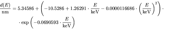
The depth of the tail region has a maximum at an implantation energy around
30 keV as shown in Fig. 5.22. The stars in Fig. 5.22 represent
the simulation results while the red line denotes an analytical regression of
the simulated data. This analytical function averages the statistical noise in
the simulation results which is inevitable due to the simulation method.
Since the statistical noise of the results presented in Fig. 5.22 is of
the order of 1 nm, two implantation with a slightly different number of ions
have been performed for some ion energies. Due to higher number of results a
more accurate regression function could be extracted. The
analytical function for the depth ![]() of the concentration level of
of the concentration level of
![]() cm
cm![]() in nm which describes the regression is presented in
(5.6). The energy unit applied in (5.6) is keV and the
function is valid in the energy range from 10 keV to 150 keV.
in nm which describes the regression is presented in
(5.6). The energy unit applied in (5.6) is keV and the
function is valid in the energy range from 10 keV to 150 keV.
For the above simulations a displacement energy of 25 eV for removing an oxygen atom from a stable position in silicon dioxide was assumed. This value is just an estimated value as suggested in [44], while the actual value can be in the range up to 200 eV. Since the displacement energy is suggested to have a strong influence on the oxygen distribution, this influence has been analyzed by simulation. The result of this analysis is presented in Fig. 5.23. Simulations have been performed with five different displacement energies in the interval from 15 eV to 75 eV and an implantation energy of 75 keV has been used. According to the simulations mainly the oxygen concentration near the silicon-silicon dioxide interface is reduced by increasing the displacement energy, while the concentration in the tail region remains almost unchanged.
Worth mentioning concerning this application is that the real oxygen distribution is probably slightly deeper than the simulated distribution, because a knock-on of oxygen atoms located in silicon by succeeding ions is neglected in the simulations, but the oxygen concentration in silicon is very high and thereby the probability for a collision with an oxygen atom is also high.
![]()
![]()
![]()
![]() Previous: 5.2 Effect of Pre-amorphization
Up: 5. Applications
Next: 5.4 Implantation into Topological
Previous: 5.2 Effect of Pre-amorphization
Up: 5. Applications
Next: 5.4 Implantation into Topological