Previous: 2.3.1 Conventional RESURF in JI Up: 2.3 RESURF Next: 2.3.3 RESURF in SOI
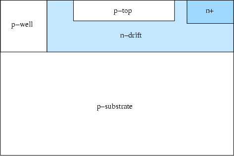
A similar RESURF effect can be achieved in multiple junction devices where an
additional layer of opposite doping (![]() -top region in Figure 2.21) is incorporated
in the
-top region in Figure 2.21) is incorporated
in the ![]() -drift region. The main purpose of this structure is to increase the
optimum charge in the drift region without reducing the BV.
In such structures the vertical depletion
of the
-drift region. The main purpose of this structure is to increase the
optimum charge in the drift region without reducing the BV.
In such structures the vertical depletion
of the ![]() -drift region is supported by two (or three) junctions.
Because of the multi vertical depletion in the device, the total
integrated charge
-drift region is supported by two (or three) junctions.
Because of the multi vertical depletion in the device, the total
integrated charge ![]() in the
in the ![]() -drift layer can be increased allowing the on-resistance
to be decreased compared to single-RESURF devices. In order to maintain
a high BV in the multi-RESURF devices, it is required that both the
-drift layer can be increased allowing the on-resistance
to be decreased compared to single-RESURF devices. In order to maintain
a high BV in the multi-RESURF devices, it is required that both the
![]() -top and the
-top and the ![]() -drift regions are fully depleted.
-drift regions are fully depleted.
Figure 2.21 shows the double RESURF lateral
diode which has two vertical junctions at the ![]() -substrate/
-substrate/![]() -drift
and
-drift
and ![]() -top/
-top/![]() -drift.
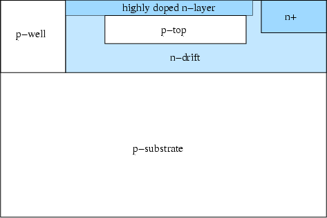
Another approach to reduce the on-state resistance is to use dual conducting
paths in the
-drift.
Another approach to reduce the on-state resistance is to use dual conducting
paths in the ![]() -drift.
-drift.
Figure 2.22 shows the RESURF lateral device which has two
current path in the ![]() -drift. In this figure a
-drift. In this figure a ![]() -buried layer is added inside of
the
-buried layer is added inside of
the ![]() -drift in the drift region. With this
-drift in the drift region. With this ![]() -buried layer
-buried layer ![]() -drift charge can be
increased compared to that of the double RESURF structure.
To decrease further the on-resistance
the highly doped and thin
-drift charge can be
increased compared to that of the double RESURF structure.
To decrease further the on-resistance
the highly doped and thin ![]() -layer can be added on the top of the buried
-layer can be added on the top of the buried ![]() -layer.
But the floating
-layer.
But the floating ![]() -buried layer will give poor BV performance, it must be grounded
by contacting to the
-buried layer will give poor BV performance, it must be grounded
by contacting to the ![]() -well.
-well.
By adding the ![]() -layer the
-layer the ![]() -buried layer doping has to be increased to achieve
charge balance in the off-state. This
-buried layer doping has to be increased to achieve
charge balance in the off-state. This ![]() -layer forms a current conduction
path which reduces the on-state resistance.
For the double-RESURF structure shown in Figure 2.21, it is essential
that the doping concentration of the
-layer forms a current conduction
path which reduces the on-state resistance.
For the double-RESURF structure shown in Figure 2.21, it is essential
that the doping concentration of the ![]() -top region (
-top region (
![]() ) is sufficiently large
that
) is sufficiently large
that
![]() >
>
![]() >
>
![]() .The breakdown point is at
the lateral
.The breakdown point is at
the lateral ![]() -top junction with BV given by
-top junction with BV given by
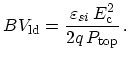 |
(2.11) |
As was stated earlier, in order to achieve a high BV in the
double-RESURF structure, full depletion of the ![]() -top and
-top and ![]() -drift regions is
required. Here, just like in the case of single-RESURF devices, full depletion
should occur before the lateral
-drift regions is
required. Here, just like in the case of single-RESURF devices, full depletion
should occur before the lateral ![]() -top junction breaks down.
Therefore, in the double-RESURF case, the following conditions must be fulfilled
-top junction breaks down.
Therefore, in the double-RESURF case, the following conditions must be fulfilled
| (2.12) |
| (2.13) |
where
![]() is the vertical depletion extension
into the
is the vertical depletion extension
into the ![]() -top region at
-top region at
![]() ,
,
![]() is
the junction depth of the
is
the junction depth of the ![]() -top region, respectively.
-top region, respectively.
![]() is
the vertical depletion extension into the
is
the vertical depletion extension into the ![]() -drift region
from the
-drift region
from the ![]() -top/
-top/![]() -drift junction and
-drift junction and
![]() is the vertical depletion extension into the
is the vertical depletion extension into the ![]() -drift region from the
-drift region from the
![]() -substrate/
-substrate/![]() -drift junction.
-drift junction.
(2.12) prevents the structure from breaking down prematurely at the
lateral ![]() -top, whereas (2.13) guarantees the prevention
of a premature breakdown at the lateral
-top, whereas (2.13) guarantees the prevention
of a premature breakdown at the lateral ![]() -drift junction.
With this structure the total charge in the
-drift junction.
With this structure the total charge in the ![]() -drift region can be increased twice
as much as in single-RESURF structure, leading to a much lower on-resistance.
-drift region can be increased twice
as much as in single-RESURF structure, leading to a much lower on-resistance.
Jong-Mun Park 2004-10-28