 .
.
Using the task-level encapsulation mechanisms presented in
Chapter 8, the complete analysis and optimization task
outline above can be defined in VISTA/SFC by a list of statements.
Figures 9.6 through 9.10
show the code for batch-mode operation .
.
In Figure 9.6, the first statement defines a new project that uses a process flow description file. (The LAT implant is realized by using two subsequent implantation steps, POCKET-L and POCKET-R, of opposite implantation angles). Table 9.3 lists the relevant process parameters and responses. The second statement creates an EVE object to manage all experiments of the optimization task. The symbolic name "flow-eve" is assigned to identify this object unequivocally in the case several EVE instances exist simultaneously.
The Eve-Define-Control statements (cf. Section 8.4.1) define the position of the experimental control variables in the process flow. For example, the implantation angle anginc in the process step labeled POCKET-R is assigned the symbolic name PAR. The value of PAR is derived from the value of the control variable PA by multiplying with -1, leading to symmetric implantation profiles. The Eve-Set-Control statements define default values and ranges for the control variables.
Responses are defined with the Eve-Define-Control statement. In the example the device simulation generates sets of data points for gate voltages between 0 V and the drain bias vd. Using the LISP functions last and first to derive the values of the response variables from these sets is a simple way to get the minimum and maximum drain current and bulk current values.
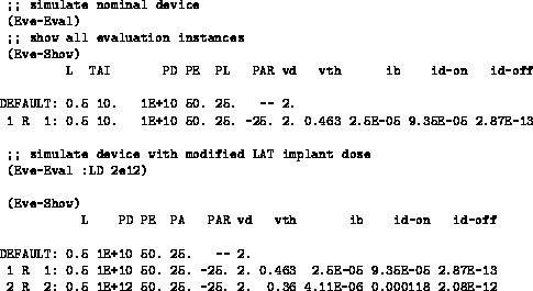
Once the controls and responses are defined, the Eve-Eval statement is used to simulate the nominal device. After termination of the simulation, the results can be examined (Figure 9.7). Parameter value settings can be given to study interactively the behavior of the design.

Figure 9.7:
The simulation of the nominal device is started by using the
Eve-Eval command. Parameter value settings can be given. Note that
ib represents ![]() times the maximum bulk current (see
Figure 9.6).
times the maximum bulk current (see
Figure 9.6).
Figure 9.8 shows the VISTA/SFC sequence statement calling three DoE steps to create two times
7 experiments, varying
the gate length L from
 ![]() to
to ![]() in equidistant
steps for PD set to
in equidistant
steps for PD set to ![]() and
and ![]() , respectively,
plus 15 experiments from a full-factorial CCI design for the three
process parameters.
The Eve-Stop command prevents the new
experiments from being submitted for simulation immediately;
Eve-Start starts evaluation for all 29 scheduled instances.
They are run simultaneously by the run controller and distributed
across the network.
, respectively,
plus 15 experiments from a full-factorial CCI design for the three
process parameters.
The Eve-Stop command prevents the new
experiments from being submitted for simulation immediately;
Eve-Start starts evaluation for all 29 scheduled instances.
They are run simultaneously by the run controller and distributed
across the network.

Figure 9.8:
Design of experiments for screening analysis of LAT implant.
The DoE module is called for the design type SA and override nominal
settings for the dose parameter PD.
The sequence operator is used to chain a sequence of asynchronous LISP
commands.
After computation of the sample points, a response surface is built
from the data generated for the three responses vth, ib, and id-on.
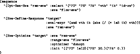
Figure 9.9 shows the sequence of statements to
run the RSM generator, define a target function for the optimization
process, and start the optimization for a set of initial values.
From the available optimizers, the donopt program
is selected. The target function for the optimizer is constructed
from the threshold and maximum bulk current values to raise
the threshold voltage at L=
for the three responses vth, ib, and id-on.
Figure 9.9 shows the sequence of statements to
run the RSM generator, define a target function for the optimization
process, and start the optimization for a set of initial values.
From the available optimizers, the donopt program
is selected. The target function for the optimizer is constructed
from the threshold and maximum bulk current values to raise
the threshold voltage at L=![]() and keep the bulk current as
low as possible.
and keep the bulk current as
low as possible.

Figure 9.9:
VISTA/SFC statements for RSM model generation and optimization.
If one wishes to run the optimizer directly on the simulation server, the RSM generation step is skipped and the target function is defined directly in the "flow-eve" object to provide input for the optimizer (Figure 9.10).