Tool specialization has led to expert tools dealing with isolated
aspects of a wafer only. For example, the
SAMPLE [ONS![]() 80] [Ele91] and
PROMIS [SS95] etch and deposition modules operate
only on the wafer geometry, causing inconsistencies between
the grid-based dopant distribution data and the
geometry boundary information, as they do not take care of reconciling
the two after updating the geometry
80] [Ele91] and
PROMIS [SS95] etch and deposition modules operate
only on the wafer geometry, causing inconsistencies between
the grid-based dopant distribution data and the
geometry boundary information, as they do not take care of reconciling
the two after updating the geometry .
To ensure a correct, consistent, and concise wafer
representation after each process simulation step, data merge
operations have to be performed to reflect geometry alterations in the
grid structure, to purge superfluous grid elements, and to merge dopant
information from before and after a simulator call
(cf. Figure 4.4).
Figure 4.8 sketches the data flow in the case of a PROMIS
etch operation.
.
To ensure a correct, consistent, and concise wafer
representation after each process simulation step, data merge
operations have to be performed to reflect geometry alterations in the
grid structure, to purge superfluous grid elements, and to merge dopant
information from before and after a simulator call
(cf. Figure 4.4).
Figure 4.8 sketches the data flow in the case of a PROMIS
etch operation.
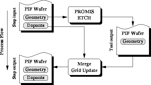
Figure 4.8:
Data flow for creating a consistent wafer
model after a PROMIS etch operation.
Starting from the geometry information present in the PIF wafer state
model, the tool call generates the new wafer geometry reflecting the
effects of the simulated etch or deposition process. In the subsequent merge
and update operation, segment grids on all segments of the geometry
are checked and adjusted to conform with their respective
segments.
After the merge and grid-update operation, a complete model of the
wafer is available for further processing.
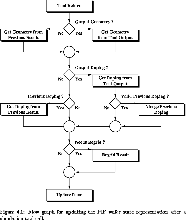
For the general case, Figure 4.9 shows the basic flow
graph for updating the PIF wafer state representation after
termination of a tool.