7.6 Memory and Runtime Benefits in FEM applications
Volumetric meshes are widely used for simulations, especially discretization-based simulations like the FEM.
This section covers memory savings of templated meshes, where also the memory usage of a FEM simulation is considered.
Up to this point, memory savings are calculated by taking the quotient of the memory usage of a templated mesh and the memory usage of a conventionally generated mesh.
The memory savings in this section, however, also include the required memory for a FEM simulation for the templated mesh and the conventionally generated mesh.
The FEM discretization is usually stored using a square matrix, called the system matrix, which is commonly sparse [103]. The size and the sparsity pattern of that matrix depends on the topology of the mesh on which the simulation is carried out. Different sparse matrix formats have been proposed.
For example, the compressed sparse row (CSR) format, which is used in this work, is a reasonable, general purpose sparse matrix storage format which usually allows for good performance [141].
When using linear FEM, the focus in this section, the unknowns in the system matrix can be identified with the mesh vertices.
A naive approach for storing the system matrix of a templated mesh is to use the system matrix of its structure instance.
Memory benchmark results which include the required memory size for the system matrix of a linear FEM using this naive approach are given in Figure 7.16.
It can be seen that the memory savings which include the system matrix sizes are significantly lower than the memory savings without the system matrix sizes. Memory savings including the system matrix only range from one (no saving) to three.
Figure 7.16:
Memory benchmark results including the FEM system matrix
|
The memory savings including the system matrix are calculated using the quotient of the memory usage of the conventionally generated meshes plus the memory usage for its system matrix and the memory usage of the templated mesh plus the usage of the system matrix of its structure instance. The rotationally symmetric objects  -polygon and the open TSV structure presented in Section 7.3 are used for this benchmark. -polygon and the open TSV structure presented in Section 7.3 are used for this benchmark. |
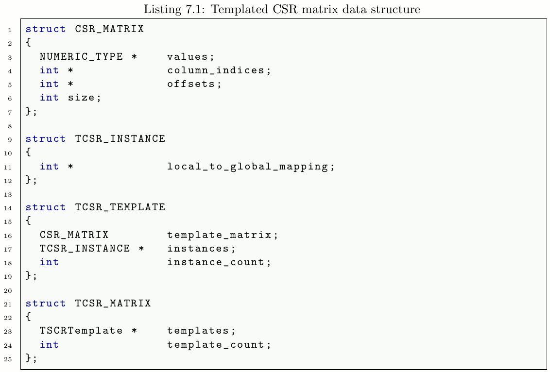
However, it is possible to use a templated approach for storing the system matrix. Listing 7.1 presents the TCSR_MATRIX data structure which represents the system matrix of a templated mesh which uses a templated approach for memory optimization. For each mesh template its system matrix is calculated as usual assuming that every mesh template vertex is an unknown. This template matrix is stored in the CSR format using the CSR_MATRIX data structure. Additionally, for each instance a mapping is required to map the local unknowns to global unknowns. This is achieved by the local_to_global_mapping in the templated CSR matrix data structure.
If the instance of a template mesh vertex within the structure instance is part of a Dirichlet boundary and therefore not an unknown, the corresponding mesh vertex is mapped to an invalid value, i.e., to  , for that particular mesh instance.
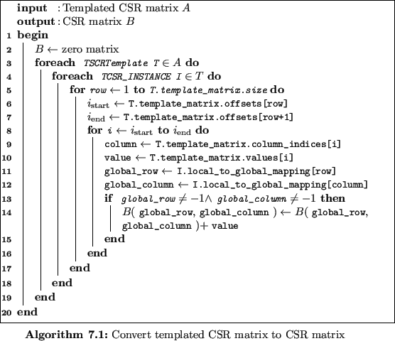
Using this mapping, a templated CSR matrix can be converted to a classical CSR matrix using Algorithm 7.1.
This algorithm iterates over all instances of all templates and adds the matrix entries of the local template matrix to the corresponding global CSR matrix entries using the local_to_global_mapping. Vertices which are on the inside of an instance only have neighbor vertices inside that instance.
Therefore, these global unknowns are updated only once in the global CSR matrix. For a local unknown, which associated vertex is in any instance interface, the local coupling with neighbor vertices is only calculated using the local cell connections. When transforming these local vertices to the structure instance, the sum in Line 14 (cf. Algorithm 7.1) adds up all valid couplings of all mesh instances in which the vertex is.
This sum reflects the linearity of the inner product which is used to calculate the coupling for a FEM problem. Additionally, the evaluation of that coupling is invariant under rigid transforms [103]. Therefore, the resulting CSR matrix of Algorithm 7.1 with the input being a templated CSR matrix based on a templated mesh will be the same as the CSR matrix of its structure instance.


Solution methods for FEMs are typically based on iterative algorithms utilizing Krylov subspaces, for example the conjugate gradient algorithm [141].
One main advantage of Krylov subspace methods is, that the system matrix is not altered. The main matrix operation used in each iteration step is the matrix-vector product.
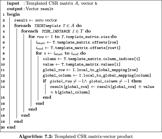
The matrix-vector product for a templated CSR matrix is presented in Algorithm 7.2.

Memory benchmark results using the templated CSR matrix data structure rather than a (classical) CSR matrix of the structure instance are presented in Figure 7.17. The memory savings including the system are significantly higher when using the templated CSR matrix data structure instead of using a CSR matrix of the structure instance. When storing the templated mesh using the data structure with SVB, the memory savings including the templated system matrix are as good as the case without considering the system matrix (compare Figure 7.17b and Figure 7.17d). In some cases, the memory savings including the templated system matrix are even better than the memory savings which do not consider any system matrix because the overhead of the shared vertex bookkeeping is less significant.
The templated CSR matrix-vector product algorithm, however, is more complex due to the additional array lockup in Algorithm 7.2, Lines 11 and 12. Runtime benchmarks for the matrix-vector product using a CSR matrix and a templated CSR matrix are given in Figure 7.18.
The matrix-vector product using a templated CSR matrix is about two to six times slower than the matrix-vector product using a conventional CSR matrix.
Therefore, the solution process is also expected to take two to six times longer. This might be an issue, if computation times are important. However, for memory-limited computing platforms the templated CSR matrix approach supports larger simulation meshes.
For most typical FEM applications, like fluid dynamics or electronic device simulation, linear solvers suffer from slow convergence as well as lack of robustness [141]. To compensate these issues, preconditioners are used. Black-box preconditioners, like the ILU factorization or the block Jacobi preconditioner, require access to the entries of the system matrix.
Accessing entries of the system matrix is a potential issue when using the templated CSR matrix data structure, because the system matrix entries of boundary vertex unknowns are not directly provided in the templated CSR matrix data structure.
However, matrix-free preconditioners are an active field of research and complement the presented approach based on templated CSR matrices [45][117].
Figure 7.17:
Memory benchmark results using the templated CSR matrix
|
Memory savings for the templated mesh including the templated CSR matrix are calculated based on the memory usage of a conventionally (non-symmetric) mesh including the memory usage of its CSR matrix. |
Figure 7.18:
Runtime benchmark results for templated CSR matrix-vector product
|
Relative runtime values are calculated by the relation of the templated CSR matrix-vector product runtime and the CSR matrix-vector product of the conventionally generated mesh system matrix. A correlation between runtime values and the number of cells can only be observed for the 2D  -polygon structures. For the 3D open TSV structures, no correlation can be observed because the number of neighbor vertices is less restricted (compared to 2D high quality meshes) in high quality 3D meshes. -polygon structures. For the 3D open TSV structures, no correlation can be observed because the number of neighbor vertices is less restricted (compared to 2D high quality meshes) in high quality 3D meshes. |
florian
2016-11-21
![\begin{subfigure}
% latex2html id marker 17372
[b]{0.48\textwidth}
\centering
...
...hmark/circle_size_cc_matrix}
\caption{$n$-polygon without SVB}
\end{subfigure}](img1725.gif)
![\begin{subfigure}
% latex2html id marker 17378
[b]{0.48\textwidth}
\centering
...
...mark/circle_size_cc_matrix_SVB}
\caption{$n$-polygon with SVB}
\end{subfigure}](img1726.gif)
![\begin{subfigure}
% latex2html id marker 17386
[b]{0.48\textwidth}
\centering
...
...k/tsv_size_cc_matrix}
\caption{Open TSV structure without SVB}
\end{subfigure}](img1727.gif)
![\begin{subfigure}
% latex2html id marker 17392
[b]{0.48\textwidth}
\centering
...
.../tsv_size_cc_matrix_SVB}
\caption{Open TSV structure with SVB}
\end{subfigure}](img1728.gif)

![\begin{subfigure}
% latex2html id marker 17482
[b]{0.48\textwidth}
\centering
...
...le_size_cc_matrix_templated}
\caption{$n$-polygon without SVB}
\end{subfigure}](img1734.gif)
![\begin{subfigure}
% latex2html id marker 17488
[b]{0.48\textwidth}
\centering
...
...e_size_cc_matrix_SVB_templated}
\caption{$n$-polygon with SVB}
\end{subfigure}](img1735.gif)
![\begin{subfigure}
% latex2html id marker 17496
[b]{0.48\textwidth}
\centering
...
..._cc_matrix_templated}
\caption{Open TSV structure without SVB}
\end{subfigure}](img1736.gif)
![\begin{subfigure}
% latex2html id marker 17502
[b]{0.48\textwidth}
\centering
...
...cc_matrix_SVB_templated}
\caption{Open TSV structure with SVB}
\end{subfigure}](img1737.gif)
![\begin{subfigure}
% latex2html id marker 17515
[b]{0.48\textwidth}
\centering
...
...rk/circle_matrix_benchmarks}
\caption{$n$-polygon without SVB}
\end{subfigure}](img1738.gif)
![\begin{subfigure}
% latex2html id marker 17521
[b]{0.48\textwidth}
\centering
...
...nchmark/tsv_matrix_benchmarks}
\caption{3D open TSV structure}
\end{subfigure}](img1739.gif)