


Next: 8.2.1 Computation Efficiency
Up: 8. Technology Optimization
Previous: 8.1.4 Configuring the Optimization
Having defined all necessary models as well as the optimization
experiment we are ready to submit our example to
SIESTA. Figure 8.7 shows the GUI which allows to
track the state of the optimization procedure. All the data which can
be viewed by selecting items of this status tree are also available
for off-line viewing. This means that one can monitor an optimization
and its progress also by viewing it with a separate program. This is
especially important if someone needs to track an optimization
remotely using a network connection. Moreover, off-line monitoring is
convenient if the optimization is performed in batch mode without a
GUI. Batch operation can be necessary if the complete optimization
is done remotely using a slow network connection.
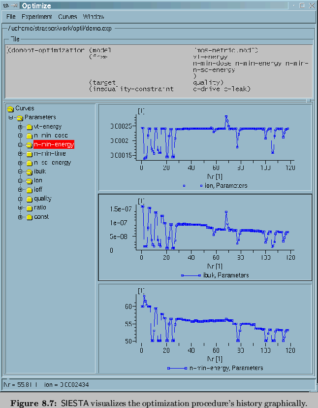
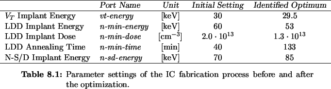
Table 8.1 summarizes the initial settings of process
parameters and their final values as result of the optimization
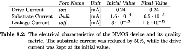
procedure. The electrical parameters of device are summarized in
Table 8.2.
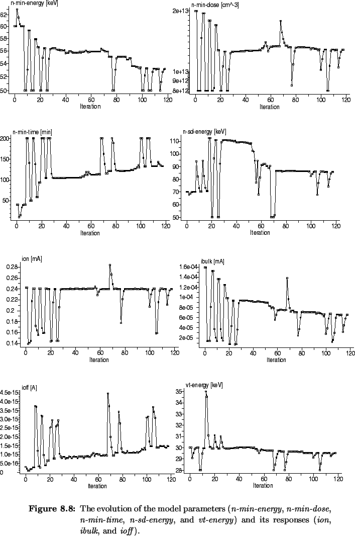
The attempts of the optimization tool to improve the target are
displayed in Figure 8.8. The parameters of the
fabrication process are displayed in the left column of
Figure 8.8 and on the very bottom of its right
column. One can see from the history of the substrate current
ibulk that the optimizer is able to successively improve the fabricated devices
in terms of the substrate current, while the drive current
ion is kept at its initial value due to the optimization
constraint. The history of the substrate current
(Figure 8.8, ibulk) shows that it is reduced
by approximately 50% to
 compared
to the initial value of
compared
to the initial value of
 .
.
Next: 8.2.1 Computation Efficiency
Up: 8. Technology Optimization
Previous: 8.1.4 Configuring the Optimization
Rudi Strasser
1999-05-27