Next: 4.1.1 Local Threshold and Up: 4. The Charge-Pumping Technique Previous: 4. The Charge-Pumping Technique
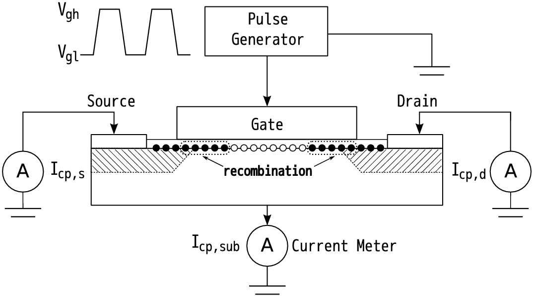
The basic charge pumping experiment setup and working principles will be described in this Section. The experimental setup performance is shown in Figure 4.1. The MOSFET source and drain are tied together and slightly reverse biased. The time varying gate voltage is of sufficient amplitude for the surface under the gate to be driven into inversion and accumulation. The pulse train can be square, triangular, trapezoidal, sinusoidal, or tri-level. The charge pumping current is measured using an ammeter at the substrate, at the source/drain connection, or at the source and drain separately.