6.2.7 Examples
In this section, two representative application examples are discussed based on two
ViennaMOS modules. The general design and usage of the modules is depicted as well as
the basic utilization of the ViennaMOS GUI and visualization backends. More concretely, the
already mentioned device generation module is introduced which provides different ways to
generate a simulation domain. Upon the module’s execution, the generated device is stored in
the central database. The second module, a device simulation module based on
the previously introduced device simulation framework ViennaMini (Section 4.3),
utilizes the device generated by the device generation module to conduct a device
simulation.
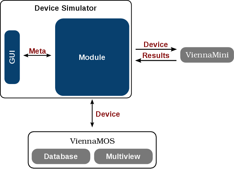
These examples further underline the advantages of the decoupled approach discussed
throughout this thesis as depicted in Figure 6.1. Not only libraries are reused by the individual
modules, but also another framework - ViennaMini - is utilized via ViennaMOS modules.
Therefore, additional development overhead is drastically minimized, as already
available implementations, such as mesh generation or device simulation facilities, are
reused.
Device Generation Module
In this section a device generation module is discussed providing the means to generate
devices for device simulations via the ViennaMini framework (Section 4.3.3). This example
also underlines the versatility of ViennaMOS modules, as this particular module is in fact not
a simulation module, but a modeling tool required to characterize the simulation domain. To
this end, the module requires mesh generation capabilities and the ability to assign a doping
profile and segment roles. Overall, the module utilizes the various device generation
functionalities enabled by interfacing with external tools, such as ViennaMini, and provides a
flexible GUI for the process, further underlining the benefit of rigorously applying a LCSD
approach.
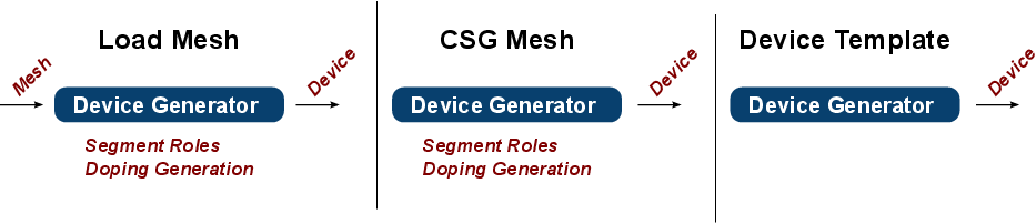
The device generation module provides three mechanisms to generate a device. Where
the first mode loads an externally generated already meshed structure enabling the end user
to assign segment roles as well as a doping profile, the second mode allows to perform an
in-place mesh generation for a desired device structure via a constructive solid
geometry ( CSG) language (primarily of interest to advanced users) also requiring the
end user to provide segment roles as well as doping information. The third mode
utilizes a device template mechanism, already providing default segment and doping
information. Figure 6.17 schematically depicts the individual device generation
modes.
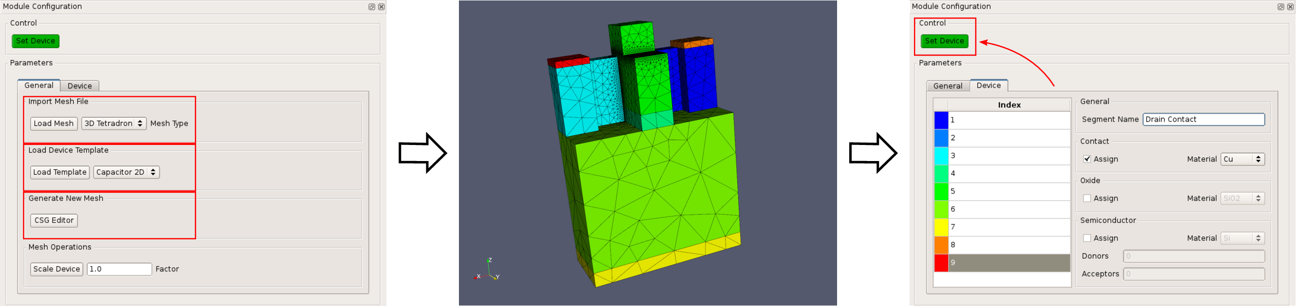
Figure 6.18 depicts the module’s GUI and the basic process flow. The end user
selects one of the three device generation mechanisms. As soon as the structure is
loaded, the render window visualizes the mesh. Finally the GUI provides the means to
assign segment roles including doping levels for semiconductor segments. When
the end user is finished, the device can be stored into ViennaMOS’ central data
storage, so other modules can access it. In this particular case, a FinFET device is
prepared, offering the same properties as depicted in Section 4.3.10. This device is
used in the subsequent device simulation steps, therefore it is stored in the central
database.
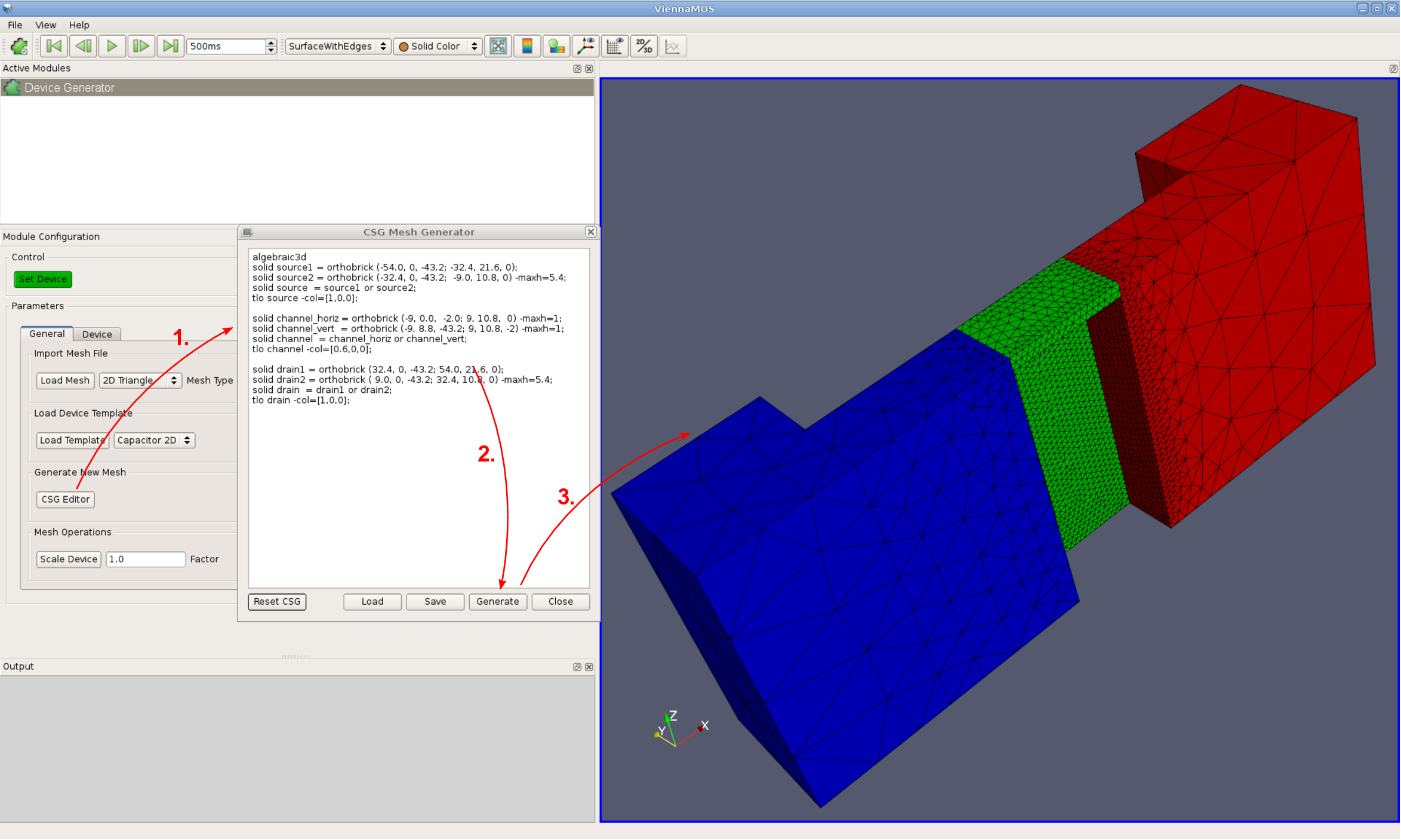
Aside from the already discussed structure loading and device template mechanism, a
peculiarity of this module is the CSG functionality. ViennaMesh provides an interface to
Netgen’s three-dimensional CSG backend, enabling on-the-fly generations of meshed
structures inside the device generation module. Due to the applied LCSD approach, the
module’s GUI has to provide merely a text input field - holding the CSG commands - which is
forwarded to the CSG backend via ViennaMesh.
In turn, ViennaMesh takes care of transferring the generated mesh into an appropriate
ViennaGrid mesh object. Figure 6.19 depicts the utilization of the CSG mechanism.
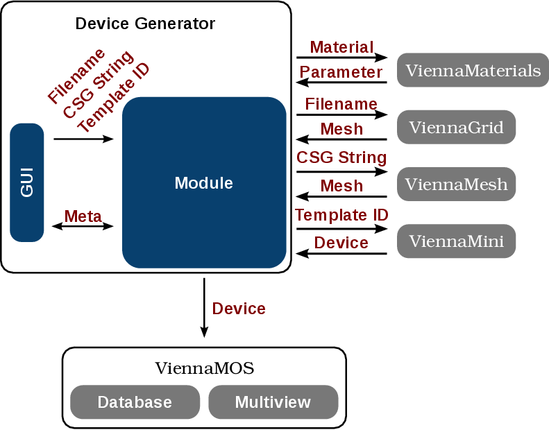
The implementation of the device generation module is based on two classes, separating
the GUI from the actual module implementation interfacing with external libraries
(Figure 6.20). The GUI forwards the input data to the module according to the chosen
generation mode. For instance, if the CSG mode is used, a string containing the CSG
information is passed. The module makes use of synergy effects in particular by interfacing
with ViennaGrid, ViennaMesh, ViennaMini, and ViennaMaterials for loading and
generating meshes, accessing material data as well as using the device template
mechanism, respectively. The thus received data is used to update the GUI, allowing the
end user to customize the device by, for instance, updating the segment roles and
doping information. Finally, if the end user is finished, the device is forwarded to the
framework, where it is stored in the central database for other modules to access
it.
Device Simulation Module
This section introduces a device simulation module providing basic device simulation
capabilities. The module is a wrapper for the previously introduced device simulation
framework ViennaMini (Section 4.3), further underlining the benefit of decoupling
functionality into reusable tools by the LCSD approach. Also, the fact that this module is
merely a wrapper puts the focus of this section on the module itself rather than discussions
regarding the simulation results.
With respect to the implementation, the device simulator module interfaces with
ViennaMini and provides a GUI for the provided API (Figure 6.21). The device simulation
module becomes usable, i.e., it can be selected in the active module list of the main
ViennaMOS GUI (Section 6.2.6), as soon as a valid device is stored in the ViennaMOS
central data storage. The device is automatically imported and the GUI is updated accordingly,
enabling the end user to setup contact potentials or currents as well as particular
physical models. Upon the module’s execution the ViennaMini-powered simulation is
conducted.
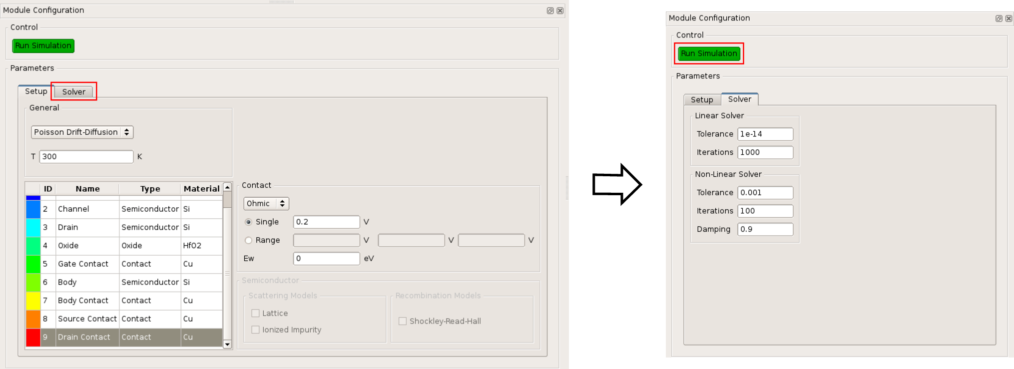
Figure 6.22 shows a basic but representative populated device simulation GUI based on
the FinFET device generated by the previously executed device generation module. The GUI
provides an overview of the device segments and related meta information, generated
by the previously utilized device generation module. The device simulation setup
is segment-based, meaning that the end user can assign contact potentials and
semiconductor models, like scattering models, for each segment. The actual simulation is
triggered via the corresponding execution button. When the simulation is finished, the
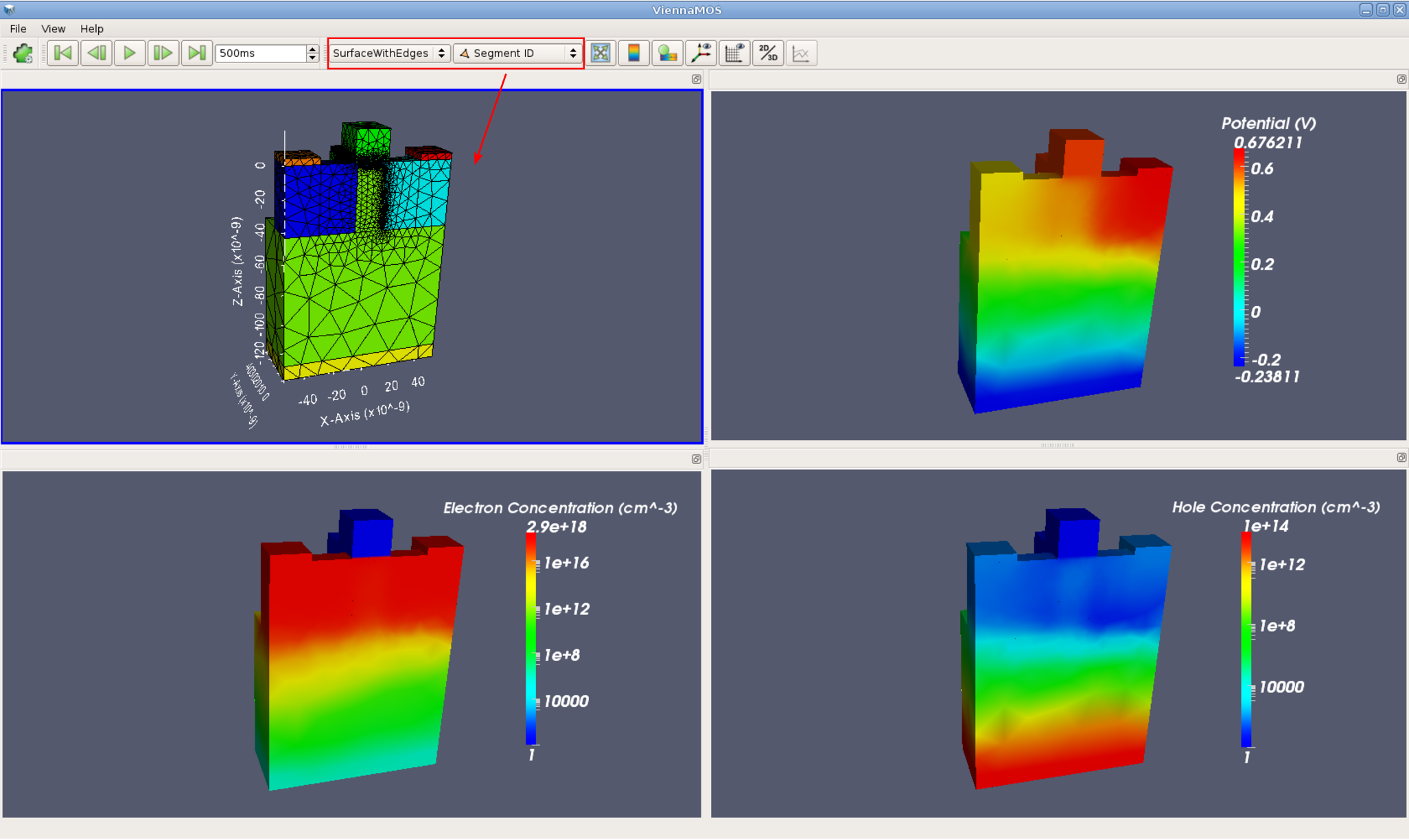
results can be visualized by ViennaMOS’ multiview mechanism (Figure 6.23). In this
particular case a similar simulation - an active FinFET device - as introduced in
Section 4.3.10 has been conducted. Note that the current limitations of the visualization
mechanism do not allow for manual color ranges, therefore if logarithmic color rendering
is required - as is the case for the electron concentration and hole concentration
distributions - segments offering no quantity values are automatically assigned a
value of one to enable the computation of the logarithm. This manifests with the
carrier concentration distributions’ renderings where the gate is assigned a value of
one.