Here, we will sketch results obtained by the Analytical Ion
Implantation Module and compare them with Monte Carlo simulations
obtained by the Monte Carlo Implant Module of PROMIS. Using
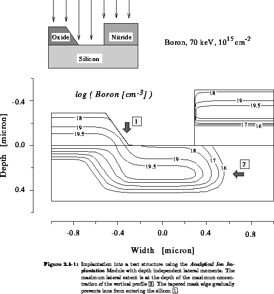
a test structure (Figure 2.5-1) we will elaborate three
important factors to be taken into account for accurate treatment of
two-dimensional ion profiles - tapered mask layers, lateral moments
 vary with depth and the effect of the beam
tilt angle.
vary with depth and the effect of the beam
tilt angle.
Masking layers are often tapered at the edge rather than perfectly abrupt,
so that ions are gradually prevented from entering the silicon. Note that
the ions penetrate through the thinner region of the sloping mask and
increase the doping near the corner (Figure 2.5-1  ).
The concentration profile in Figure 2.5-1 was calculated using
constant lateral moments and, therefore, the maximum lateral extent of the
profile under the nitride mask is at the depth of the maximum concentration
of the vertical profile (Figure 2.5-1
).
The concentration profile in Figure 2.5-1 was calculated using
constant lateral moments and, therefore, the maximum lateral extent of the
profile under the nitride mask is at the depth of the maximum concentration
of the vertical profile (Figure 2.5-1  ).
).
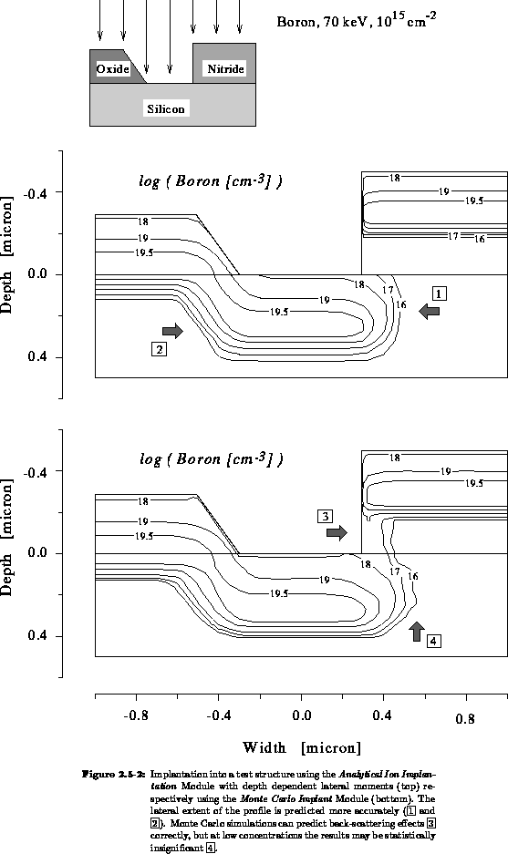
Using the more sophisticated model including depth dependent lateral moments
(top in Figure 2.5-2) the lateral shape of the profile is
predicted more accurately (Figure 2.5-2 ) and the
lateral extent underneath the tapered mask is not overestimated
(Figure 2.5-2 ).
The agreement of these results
with Monte Carlo simulations is quite good. One detail is not (and cannot
be) reproduced by the analytical model. Ions scattered into free space
travel without scattering until they reenter the target, e.g. nitride
 silicon and vice versa
(Figure 2.5-2
silicon and vice versa
(Figure 2.5-2  ). For the Monte Carlo simulation we
used
). For the Monte Carlo simulation we
used  distinct trajectories which gives a total number of
 simulated ions for this geometry applying Hobler's
superposition method [Hob89]. Nevertheless, all these 16 million ion
positions are constructed from only 40,000 different trajectories.
Considering the peak concentration of
simulated ions for this geometry applying Hobler's
superposition method [Hob89]. Nevertheless, all these 16 million ion
positions are constructed from only 40,000 different trajectories.
Considering the peak concentration of  one simulated
trajectory end point gives a concentration of at least
one simulated
trajectory end point gives a concentration of at least  and, therefore, the
  contour line is statistically
insignificant (Figure 2.5-2
contour line is statistically
insignificant (Figure 2.5-2  ).
).
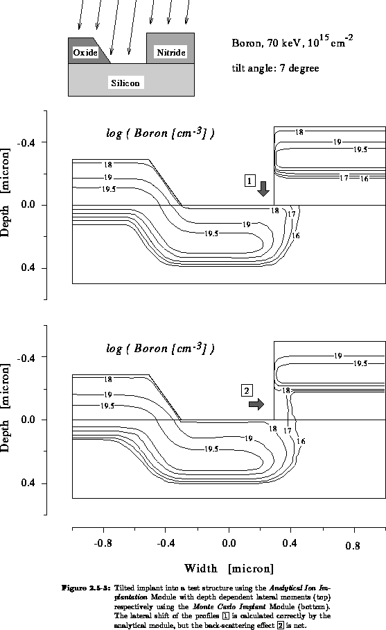
Finally, we take a closer look at the effect of a  beam tilt
angle. This tilt reduces the profile peak depth less than
beam tilt
angle. This tilt reduces the profile peak depth less than  of
of  but
shifts the profile laterally by
but
shifts the profile laterally by  of the mask height.
In modern VLSI processes the layers above the substrate have not been scaled
vertically with decreasing line width, on the contrary, with the development
of multilayer metallization the tendency is towards thicker covering layers.
Self aligned processes use the gate as an implantation mask, so a tall gate
stack can cause a significant shadow at the edge of the source or drain. In
our example we notice a lateral shift of the profile of  Å
away from the
Å
away from the  nitride mask
(Figure 2.5-3 ). Again, the agreement of the
analytical results with the Monte Carlo simulations is quite good, except for
the known back-scattering effect (Figure 2.5-3 ).
nitride mask
(Figure 2.5-3 ). Again, the agreement of the
analytical results with the Monte Carlo simulations is quite good, except for
the known back-scattering effect (Figure 2.5-3 ).