|
|
|
|
Previous: 4.4 Body Contact Up: 4. Standard Energy Transport Simulations Next: 4.6 Transient Behavior |
|
|
|
|
Previous: 4.4 Body Contact Up: 4. Standard Energy Transport Simulations Next: 4.6 Transient Behavior |
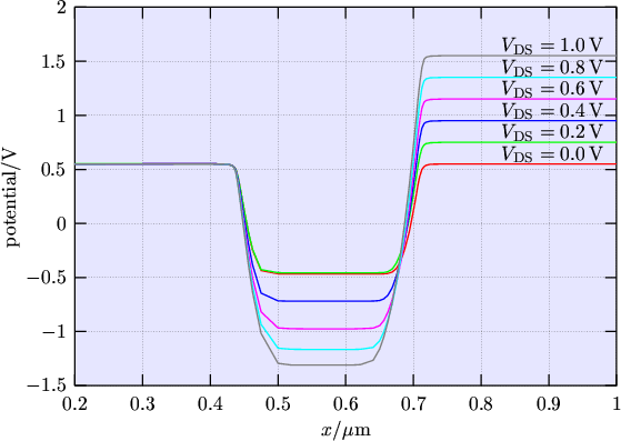 |
In Fig. 4.9 an anomalous drop of the body potential is observed with
increasing drain voltage. Not only is the drain-body junction reverse biased but also the
source-body junction. Therefore, leakage currents from both junctions flow into the floating
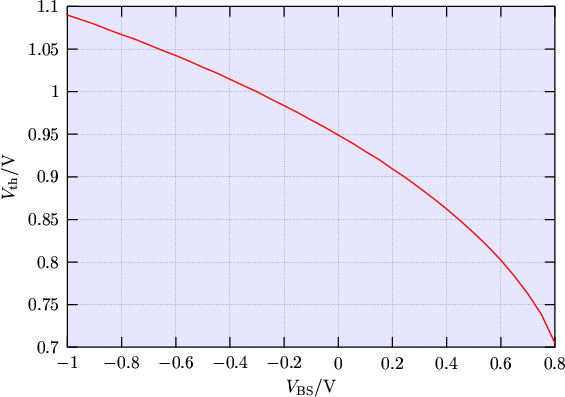
body. Clearly, the dropping body potential has an influence to the drain current via the body
effect (Fig. 4.10). The gate overdrive
![]() gets
reduced because
gets
reduced because
![]() increases while
increases while
![]() stays the same yielding to a
reduced channel charge and therefore to a smaller drain current.
stays the same yielding to a
reduced channel charge and therefore to a smaller drain current.
 |
The balance of the drift and diffusion currents is affected by carrier heating as follows.
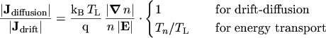 |
(4.1) |
To the occurrence of the current drop four partial effects contribute:
The RST of hot electrons from the pinch-off region to the depletion region underneath is at the outset of the effect. With drift-diffusion, the RST does not appear since electrons cannot move from the low quasi FERMI level (QFL) in the pinch-off region to any higher QFL in the depletion region or in the p-body. The difference in the electron concentration between drift-diffusion and energy transport can be seen clearly in Fig. 4.11 and Fig. 4.12. In Fig. 4.12 the spread of electrons into the body is remarkable. This difference has a great impact on the SHOCKLEY-READ-HALL generation/recombination rates depicted in Fig. 4.13 to Fig. 4.16. The critical area is the depletion region underneath the pinch-off region. While the drift-diffusion simulation predicts carrier generation in this area, which is the expected situation in this depletion region, in the energy transport simulation carrier recombination takes place because of the excess electrons. As a consequence of recombination, holes are removed from the p-body. If the body is contacted, the recombining holes are substituted by holes from the body contact, leading to a small substrate current which flows into the body (Fig. 4.7). However, in an SOI MOSFET the situation is different. The holes removed by recombination make the body potential drop. Eventually the reverse bias of the source-body and drain-body junctions becomes large enough such that the junction leakage currents compensate for the recombination current and a steady state is reached. Via the body effect the drop of the body potential causes the drain current to decrease.
![\includegraphics[width=.55\textwidth]{eps/HD_otherLimits.epsi}](img921.png) |
![\includegraphics[width=.55\textwidth]{eps/3D_Generation_DD.epsi}](img922.png) |
![\includegraphics[width=.55\textwidth]{eps/3D_Generation_ET.epsi}](img923.png) |
![\includegraphics[width=.55\textwidth]{eps/3D_Recombination_DD.epsi}](img924.png) |
![\includegraphics[width=.55\textwidth]{eps/3D_Recombination_ET.epsi}](img925.png) |
|
|
|
|
Previous: 4.4 Body Contact Up: 4. Standard Energy Transport Simulations Next: 4.6 Transient Behavior |
![\includegraphics[width=.55\textwidth]{eps/3D_n_DD.epsi}](img920.png)