5.8 Results
Based on the previous results we are now able to better understand the charge
pumping current  measured with the OFIT sequence. The presence of
additional charges contributes to the signal when the pulse amplitude
measured with the OFIT sequence. The presence of
additional charges contributes to the signal when the pulse amplitude  is increased. A large spread of time constants larger than that of the
interface states is necessary to explain the results. By assuming oxide traps
with a distributed thermally activated barrier one is able to explain the
measurement results with good accuracy. Whereas interface states seem to not
respond to an increasing electric field and due to their small time constants
account for
is increased. A large spread of time constants larger than that of the
interface states is necessary to explain the results. By assuming oxide traps
with a distributed thermally activated barrier one is able to explain the
measurement results with good accuracy. Whereas interface states seem to not
respond to an increasing electric field and due to their small time constants
account for  at low (
 ) and high frequencies (
 ), the oxide
traps are by far slower due to the assumed barrier
), the oxide
traps are by far slower due to the assumed barrier  they have to
surmount. That is why oxide traps only affect
they have to
surmount. That is why oxide traps only affect  at lower frequencies, i.e.
 .
.
The particularly troublesome part is the application of the OFIT technique
during the stress phase, where both oxide traps  and additionally created
interface states
and additionally created
interface states  add to
  . These contributions are absent during the
initial reference measurements and during the OFIT recovery measurements both
taken at
. These contributions are absent during the
initial reference measurements and during the OFIT recovery measurements both
taken at  . This has fundamental consequences on OFIT
measurements: Initially, a reference
. This has fundamental consequences on OFIT
measurements: Initially, a reference  is recorded. Following this reference
measurement, the gate voltage low-level
is recorded. Following this reference
measurement, the gate voltage low-level  is switched to
  .
Due to the much larger
.
Due to the much larger  now a significant contribution of
  is obtained. Furthermore, with the large pulse amplitude, additional
interface states are created, which is the intended effect of this OFIT
measurement. However, without this the additional increase in
is obtained. Furthermore, with the large pulse amplitude, additional
interface states are created, which is the intended effect of this OFIT
measurement. However, without this the additional increase in  due to oxide
traps must not be attributed to interface states created by degradation.
Consequently,
due to oxide
traps must not be attributed to interface states created by degradation.
Consequently,  needs to be corrected in the measurement data.
Using the mentioned extrapolation method of
needs to be corrected in the measurement data.
Using the mentioned extrapolation method of  reveals
that the 30% initial increase in
reveals
that the 30% initial increase in  is entirely due to oxide traps. The
corrected last stress value in Fig. 5.19 is identical to the first value at the
recovery, leading to the conclusion that no fast interface state recovery
occurs.
is entirely due to oxide traps. The
corrected last stress value in Fig. 5.19 is identical to the first value at the
recovery, leading to the conclusion that no fast interface state recovery
occurs.
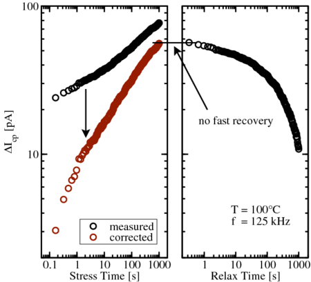
 is obtained. The smooth transition between the corrected
  during
stress and the
during
stress and the  during recovery suggests that no fast recovery takes
place.
during recovery suggests that no fast recovery takes
place.