6.2 Memristive Sensing Principles
The memristive sensing scheme explained below can be classified as a novel charge-discharge (time domain)
technique in which the capacitance or the inductance is calculated by measuring the memristance
(memductance) and thus eliminates the need for time (frequency) measurement. In fact, the
memristance (in the unit of  ) or memductance (in the unit of S
  ) of a memristor can be
simply determined by Ohm’s law, which makes the memristive sensing straightforward and fast.
Furthermore, because a memristor holds the information even if its voltage/current is turned off
(non-volatility), it allows for measurement circuits with low leakage power consumption and new
functionalities.
) of a memristor can be
simply determined by Ohm’s law, which makes the memristive sensing straightforward and fast.
Furthermore, because a memristor holds the information even if its voltage/current is turned off
(non-volatility), it allows for measurement circuits with low leakage power consumption and new
functionalities.
6.2.1 Charge-Controlled Memristors
6.2.1.1. Capacitance Sensing
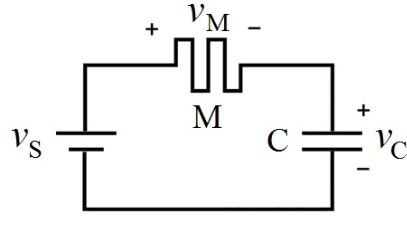
Consider a charge-controlled memristor connected in series with a capacitor as shown in Fig. 6.1. According
to Eq. 2.4 and Eq. 2.10 for the capacitance and memristance, respectively, we have
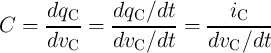 | (6.1) |
and
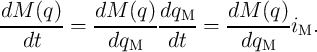 | (6.2) |
As  , by substituting
  from Eq. 6.2 into Eq. 6.1 we obtain
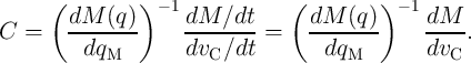 | (6.3) |
The term  is related to the intrinsic properties of the memristor. For a linear resistor this term is
zero. However, it is nonzero for a memristive device or system as it is supposed to memorize the history of
current flowing through the modulation in its memristance. A charge-controlled memristor with the term
is related to the intrinsic properties of the memristor. For a linear resistor this term is
zero. However, it is nonzero for a memristive device or system as it is supposed to memorize the history of
current flowing through the modulation in its memristance. A charge-controlled memristor with the term
 being constant is suited for charge-based capacitance sensing as it can reduce the measurement to
a simple memristance measurement. In fact, on one hand, as
being constant is suited for charge-based capacitance sensing as it can reduce the measurement to
a simple memristance measurement. In fact, on one hand, as  and
and  , we have
 . On the other hand, as for the memristor the term
  is constant, we have
  .
Therefore,
.
Therefore,  and thus
  is equal exactly to
  . As a result, Eq. 6.3 is written
as
. As a result, Eq. 6.3 is written
as
 | (6.4) |
This means that one can calculate the capacitance by measuring the modulation of the memristance and the
voltage across the capacitor (or the memristor). Therefore, unlike other time domain capacitance
measurement methods, memristive sensing does not need extra hardware for time/frequency measurement
since the time parameter has been implicitly taken into account in the memristance modulation.
Furthermore, to measure the memristance modulation, a simple circuit can be employed to switch the
memristor from the MC circuit (Fig. 6.1) to a basic readout circuit employing an arbitrary resistance read
method [96], without loosing the information during the switching due to the non-volatility of the memristor.
During the readout, the memristance and the charge in the capacitor can be reset to the initial state for
which the  and
and  are equal to
  and
and  , respectively. Then, for the next
measurement, one should measure only
, respectively. Then, for the next
measurement, one should measure only  and probably
  if the capacitor is not fully
charged (
if the capacitor is not fully
charged ( ).
).
6.2.1.2. Power Monitoring
The unique ability of a memristor to record the historic profile of the voltage/current applied makes it
suitable for power measurement [96]. The total energy generated by an electric power supply
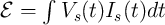 , where
  is the voltage across the source and
  is the current flowing
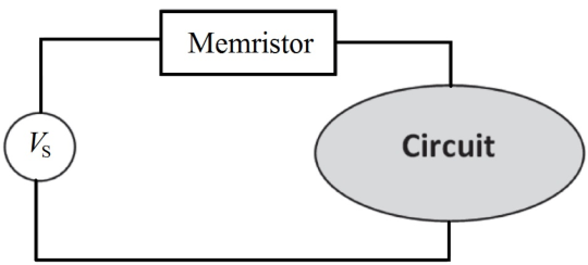
through it. For a circuit powered by a DC voltage source (Fig. 6.2) [96], the energy is given
by:
is the current flowing
through it. For a circuit powered by a DC voltage source (Fig. 6.2) [96], the energy is given
by:
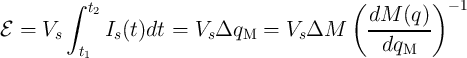 | (6.5) |
Therefore, a charge-controlled memristor with a constant term 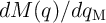 reduces the power measurement
to a memristance measurement. To minimize the impact of the memristor on measurements, the memristance
has to be much smaller than the circuit resistance.
reduces the power measurement
to a memristance measurement. To minimize the impact of the memristor on measurements, the memristance
has to be much smaller than the circuit resistance.
6.2.2 Flux-Controlled Memristors
6.2.2.1. Inductance Sensing
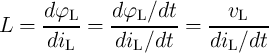
According to Eq. 2.5 and Eq. 2.11 for the inductance and memductance of a flux-controlled memristor,
respectively, we have
 | (6.6) |
and
 | (6.7) |
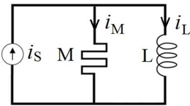
When a flux-controlled memristor is connected in parallel to an inductor ( in Fig. 6.3), the
inductance is obtained as
in Fig. 6.3), the
inductance is obtained as
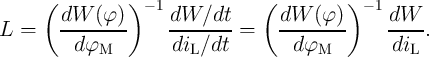 | (6.8) |
A flux-controlled memristor with a constant  term is thus suited for flux-based inductance
measurement. For a common conductor the term
term is thus suited for flux-based inductance
measurement. For a common conductor the term  is zero. However, it is nonzero for a memristive
device and is related to the intrinsic properties of the memristor. Based on a similar discussion presented
above for the MC circuit, in the ML circuit with a memristor with
is zero. However, it is nonzero for a memristive
device and is related to the intrinsic properties of the memristor. Based on a similar discussion presented
above for the MC circuit, in the ML circuit with a memristor with  , we get
  .
Therefore, Eq. 6.8 is simplified to
.
Therefore, Eq. 6.8 is simplified to
 | (6.9) |
Hence, the flux-controlled memristor in the ML circuit reduces the inductance measurement to a
straightforward memductance measurement.
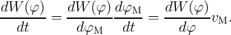
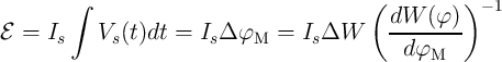
6.2.2.2. Power Monitoring
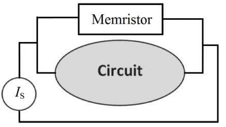
Similar to the charge-based power monitoring, in a circuit powered by a DC current source (Fig. 6.4) [96], a
flux-controlled memristor with the term  being constant reduces the power measurement to a
memductance measurement.
being constant reduces the power measurement to a
memductance measurement.
 | (6.10) |
To minimize the impact of the memristor on measurements, the memductance must be much smaller than
the circuit conductance. In the following section we study different spintronic memristors which are suited for
both charge- and flux-based measurements.