Figure 7.2 shows the structure after depositing the
inter-metal oxide and etching the contact
openings. Figure 7.3 displays the final structure of
the ring oscillator (to look into the conductors the SiO![]() material was
removed). This structure contains 1.4 million elements and the total simulation
time was 3 hours in a DEC 3000/400 workstation.
material was
removed). This structure contains 1.4 million elements and the total simulation
time was 3 hours in a DEC 3000/400 workstation.
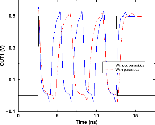
As we can see from Figure 7.1 that a drastic reduction in the oscillating frequency occurs due to the parasitic capacitors. The frequency decreased to 270MHz which corresponds to a reduction of about 25%. A better layout would avoid the interconnections between the gates of the same inverter in polysilicon. Although one extra contact per inverter would be necessary, this would improve the circuit speed by about 7.5%.
From this example, it becomes clear that the intrinsic relative fast switching
times of the devices in this technology, require a careful layout and, for
this case, interconnects with ![]() design rules would be the best choice.
design rules would be the best choice.
 |