7.1.3 Interpretation of the analytical model
The maxima of the cavity field inside and the radiated emission from the enclosure slot
are observed at the resonance frequencies, where the denominator
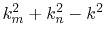 of (7.13) has its minima. At these
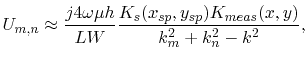
frequencies (7.13) can be approximated by the dominating term with
the minimum denominator,
of (7.13) has its minima. At these
frequencies (7.13) can be approximated by the dominating term with
the minimum denominator,
 |
(7.16) |
with the source dependent term
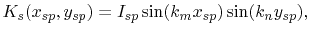 |
(7.17) |
and the term,
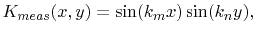 |
(7.18) |
which depends on the position of the voltage measurement. The index of  denotes
the cavity resonance mode, which is characterized by the integer pair
denotes
the cavity resonance mode, which is characterized by the integer pair  and
and  . Both
 and
and
 vanish at the metallic enclosure walls.
Therefore, placing a single current source closer to a metallic enclosure wall will
reduce the cavity field and the emissions. Below the second resonance mode, the maximum
field is in the middle of the slot at position
vanish at the metallic enclosure walls.
Therefore, placing a single current source closer to a metallic enclosure wall will
reduce the cavity field and the emissions. Below the second resonance mode, the maximum
field is in the middle of the slot at position
 and the maximum field in
every enclosure cross section
and the maximum field in
every enclosure cross section
 is located at
  . Increasing the
distance of a single source from the symmetry line will reduce the emissions up
to the second resonance frequency. The maxima of the enclosure field are at the enclosure
slot
. Increasing the
distance of a single source from the symmetry line will reduce the emissions up
to the second resonance frequency. The maxima of the enclosure field are at the enclosure
slot  for every resonance mode. According to (5.1) a trace above the
ground plane of a PCB is not a single current source, because both, the source and the
load currents, excite a cavity field. A short trace with negligible phase shift between
the source and the load current couples to the cavity with the currents
for every resonance mode. According to (5.1) a trace above the
ground plane of a PCB is not a single current source, because both, the source and the
load currents, excite a cavity field. A short trace with negligible phase shift between
the source and the load current couples to the cavity with the currents  at the
source position and
at the
source position and
 at the load position. A superposition of two terms
of (7.16), one with the excitation
at the load position. A superposition of two terms
of (7.16), one with the excitation  and the other with
the excitation
will consider the coupling from the short trace. Therefore,
this trace coupling can be investigated with the derivatives
of (7.17). Since the partial derivatives normal to the
enclosure edges have their maxima at the metallic enclosure walls, the coupling of a
differential source to the cavity is at a maximum, when it is positioned perpendicular
and close to an enclosure wall. The partial derivative in
and the other with
the excitation
will consider the coupling from the short trace. Therefore,
this trace coupling can be investigated with the derivatives
of (7.17). Since the partial derivatives normal to the
enclosure edges have their maxima at the metallic enclosure walls, the coupling of a
differential source to the cavity is at a maximum, when it is positioned perpendicular
and close to an enclosure wall. The partial derivative in  direction
of (7.17) vanishes in the symmetry line below the
second resonance. Therefore, a symmetric placement of a trace perpendicular to this
symmetry line reduces the coupling and the emissions significantly below the second
resonance of the enclosure. Both partial derivatives
of (7.17) vanish in the middle of the slot at position
up to the second resonance mode of the cavity field. Moving a differential
source to that position in an arbitrary direction will reduce the coupling to the cavity
at the first enclosure resonance. These design guidelines have been obtained simply by a
discussion of the analytical cavity model equations. Although these rules have been
extracted for the rectangular enclosure in Figure 7.1, the main
facts regarding the placement of sources and traces close, parallel or perpendicular to
metallic walls or enclosure symmetry lines can be generalized for arbitrarily shaped
enclosures.
direction
of (7.17) vanishes in the symmetry line below the
second resonance. Therefore, a symmetric placement of a trace perpendicular to this
symmetry line reduces the coupling and the emissions significantly below the second
resonance of the enclosure. Both partial derivatives
of (7.17) vanish in the middle of the slot at position
up to the second resonance mode of the cavity field. Moving a differential
source to that position in an arbitrary direction will reduce the coupling to the cavity
at the first enclosure resonance. These design guidelines have been obtained simply by a
discussion of the analytical cavity model equations. Although these rules have been
extracted for the rectangular enclosure in Figure 7.1, the main
facts regarding the placement of sources and traces close, parallel or perpendicular to
metallic walls or enclosure symmetry lines can be generalized for arbitrarily shaped
enclosures.
Perfect electrically conducting planes, air in the cavity, and a perfect magnetically
conducting boundary at the slot have been used to derive the cavity field
formulation (7.13), neglecting any losses, which leads to
significant deviations at the resonance frequencies compared to a real lossy situation.
An enclosure (Figure 7.1) usually has a much higher plane
separation  than power-ground planes on a PCB. Therefore, the radiation loss becomes
the dominant loss mechanism [45], [59], [101] and must
be considered in the cavity model to obtain a reasonably good solution. The next section
will consider the radiation loss in the cavity model and provide analytical expressions
for the calculation of the radiated emissions from the slot. A quantitative investigation
of radiated emission and coupling from sources to the enclosure will be presented based
on that model. Quantitative classification of EMC design guidelines, such as placement
and layout rules, is necessary to obtain information on their practical relevance for the
intended application. An example for the relevance of quantitative EMC rule
classification is the crosstalk from a digital signal trace to an analog circuit trace.
Whether this coupling is relevant or not depends on the spectrum of the digital signal,
the sensitivity of the analog circuit and the layout routing of the traces. A cost
optimized design cannot be reached with global rules applied to all signals. An EMC
engineer must have quantitative information, if the coupling is relevant for a decision
about shielding, trace routing, and ground separation efforts.
than power-ground planes on a PCB. Therefore, the radiation loss becomes
the dominant loss mechanism [45], [59], [101] and must
be considered in the cavity model to obtain a reasonably good solution. The next section
will consider the radiation loss in the cavity model and provide analytical expressions
for the calculation of the radiated emissions from the slot. A quantitative investigation
of radiated emission and coupling from sources to the enclosure will be presented based
on that model. Quantitative classification of EMC design guidelines, such as placement
and layout rules, is necessary to obtain information on their practical relevance for the
intended application. An example for the relevance of quantitative EMC rule
classification is the crosstalk from a digital signal trace to an analog circuit trace.
Whether this coupling is relevant or not depends on the spectrum of the digital signal,
the sensitivity of the analog circuit and the layout routing of the traces. A cost
optimized design cannot be reached with global rules applied to all signals. An EMC
engineer must have quantitative information, if the coupling is relevant for a decision
about shielding, trace routing, and ground separation efforts.
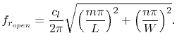
The cavity modes depend on the cavity boundaries. Parallel rectangular planes with four
open edges have been investigated for power integrity analysis purposes by [42]
and [43]. They expressed the resonances of the rectangular power planes with
 |
(7.19) |
Table 7.1 lists the resonance frequencies for the first modes
of rectangular power-planes with four open edges and of a rectangular enclosure with
three closed edges and one open slot according to Figure 7.1,
both with the same size of  =160mm and
  =120mm.
Since (7.17) and (7.18)
vanish for all
=120mm.
Since (7.17) and (7.18)
vanish for all  , the enclosure resonances with are compensated and do not
exist.
, the enclosure resonances with are compensated and do not
exist.
| |
|
power-planes |
enclosure |
|
|
 (MHz) (MHz) |
exists |
 (MHz) (MHz) |
exists |
| 0 |
0 |
0 |
no |
625 |
no |
| 1 |
0 |
938 |
yes |
1127 |
yes |
| 0 |
1 |
1250 |
yes |
1875 |
no |
| 1 |
1 |
1563 |
yes |
2096 |
yes |
| 2 |
0 |
1875 |
yes |
1976 |
yes |
|
Table 7.1:
First resonance frequencies of rectangular parallel plane cavities with
L=160mm and W=120mm and different boundaries. One with four open edges
(power-planes), the other with one open slot and three closed metal edges
(enclosure).
Power planes with four open edges have more resonances and different resonance
frequencies than the enclosure. Resonance frequencies of the same modes are shifted some
hundred MHz. In particular the first and the second resonance frequencies are interesting
with respect to the previously mentioned design rules which are related to the symmetry
line of the enclosure. In an enclosure with the dimensions =160mm, =120mm
and  , these rules are valid up to 1976 MHz, a broad band of the 2.5GHz CISPR25
frequency range according to Table 4.1.
, these rules are valid up to 1976 MHz, a broad band of the 2.5GHz CISPR25
frequency range according to Table 4.1.
C. Poschalko: The Simulation of Emission from Printed Circuit Boards under a Metallic Cover