The first optimization approach is to limit the spheres to appropriate spherical segments as depicted in Fig. 2.3(b). At corners of the structures the sphere is reduced to an eighth, at edges to a one cell thick quarter circle and within planes to a one cell thick line. By these means the final geometry as in Fig. 2.3(c) is exactly the same as when using spheres but the number of operations is drastically reduced. When using the spherical segments the CPU time is about two orders of magnitude lower than for the complete spherical algorithm. The gain in CPU time depends on the complexity of the structure. A detailed analysis of the time requirements and the reasons therefor will be given in Section 2.3.3.
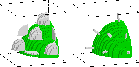 |
Corners, edges and planes are detected by checking the exposed sides of the surface cells. If only one side of the cell is exposed, the cell is considered to reside in a plane, if two cells are exposed the cell is located at an edge, with three exposed sides the cell forms a corner. The advantage of this method is, that in the case of orthogonal, even facets, as for the cube in Fig. 2.3(b) no redundant operations are introduced. However, the tradeoff is that redundancy for arbitrarily curved surfaces may be reduced only to a certain extent. The reason is that it cannot be distinguished whether a surface cell with, e.g., three exposed sides belongs to a sharp corner of the geometry or whether it is part of a curved region of the surface. The left hand side of Fig. 2.4 shows spherical segment structuring elements at selected positions for isotropic deposition onto a curved surface. It is obvious that in this constellation of the surface cells they only allow a partial reduction of the spherical segments to quarter circles. In the worst case, namely, at a plane parallel to a cube diagonal, eights of spheres can not be reduced anymore. Nevertheless using eights of spheres still gives space for an 8-fold acceleration with respect to the original spherical implementation. For this extreme case only a different method provides a solution for further algorithmic acceleration. The method is already indicated on the right hand side of Fig. 2.4 and presented next.
![]()
![]()
![]()
![]()
Prev: 2.3 Optimizations for the
Up: 2.3 Optimizations for the
Next: 2.3.2 Line Elements