m from the top of the TSV).
The simulation of the entire structure, as depicted in Fig. 4.1, is computationally unfeasible
in the presence of a large number of scallops and contact surfaces. Consequently, the
simulation domain is reduced by taking into consideration the aforementioned experimental
constraint (10m from the top of the TSV).
As boundary conditions, it was assumed that the extreme right side of the structure is fixed, while the TSV’s inner side is free to move as well as the top. The bottom boundary has a more complicated scenario, because a proper condition is unknown in the adapted domain from Fig. 5.3. To handle this situation a symmetric boundary condition was employed. Although this is not true, when the entire structure is considered, it is a good approximation for the geometry in the vicinity of the simulation domain. Additionally, it reduces any possible boundary effect which could impact the solution. The simulation was performed assuming symmetry around the central TSV axis in order to capture the cylindrical shape of the TSV.
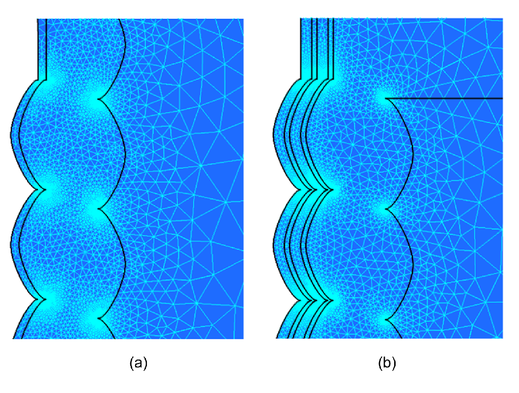
The scallop shape and the contact surfaces demand a fine mesh to prevent numerical convergence issues, as depicted in Fig. 5.6. As a result the mesh is rather dense near the scallops, leading to many mesh points and elements for a relatively small structure. Triangular elements were used, because they showed a better adaptability in this structure, when compared to quadrilateral elements. The mesh of the single stack structure has 12466 points and 24635 triangles, while the double stack structure has 17945 points and 35461 triangles.