5.2 Influence of Stress in Metal Layers on TSVs
In this section only the standard unfilled TSV is considered, as defined in Chapter 4, since
there is no relevant thin metal film in filled TSVs. The point of interest is the conduction
layer along the wall of the unfilled TSV. Any mechanical instability in this layer
can lead to cracks which, after some time, could cause a complete failure of the
TSV.
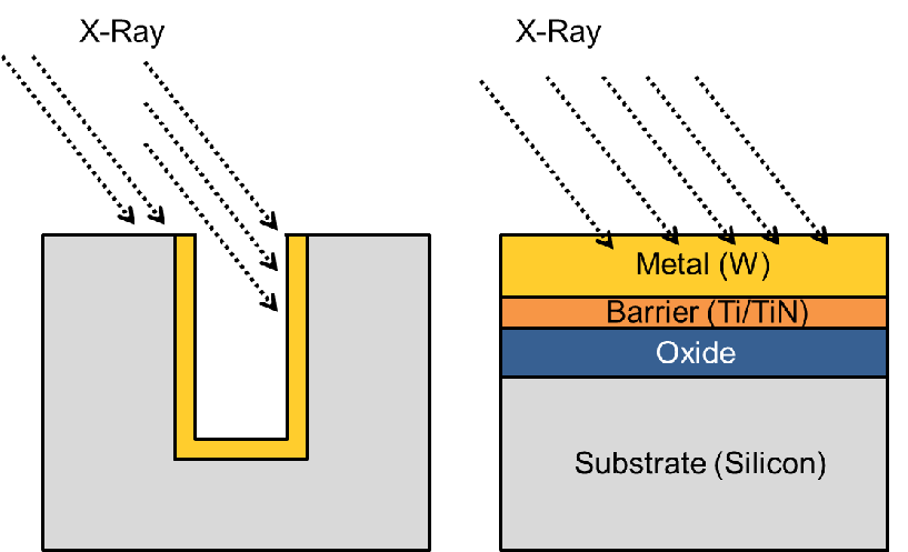
Krauss et al. [85] performed X-Ray Diffraction (XRD) stress measurements on the wall of
a standard open TSV structure, but the specific via’s geometry permitted only
a measurement of the top 10 m. A full plate sample with an identical layer
profile is then used to support stress characterization depicted in Fig. 5.1. The
purpose of the full plate is to ease the measurement process and to improve its
precision. Additionally, it represents the best estimate for the stress in the middle
of the via, since it is not feasible to measure the stress at the full depth of the
TSV.
m. A full plate sample with an identical layer
profile is then used to support stress characterization depicted in Fig. 5.1. The
purpose of the full plate is to ease the measurement process and to improve its
precision. Additionally, it represents the best estimate for the stress in the middle
of the via, since it is not feasible to measure the stress at the full depth of the
TSV.
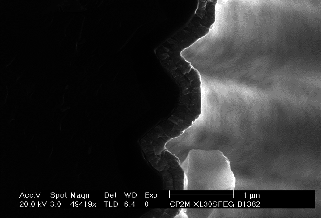
However, the stress on the TSV tungsten film was found to be smaller than on the full-plate
samples. At the TSV’s wall scallops were observed, which were caused by the Bosch process,
as depicted in Fig. 5.2. The presence of scallops along the TSV walls and the lack of them
in the full-plate sample suggests that they might be the reason behind the observed stress
reduction.
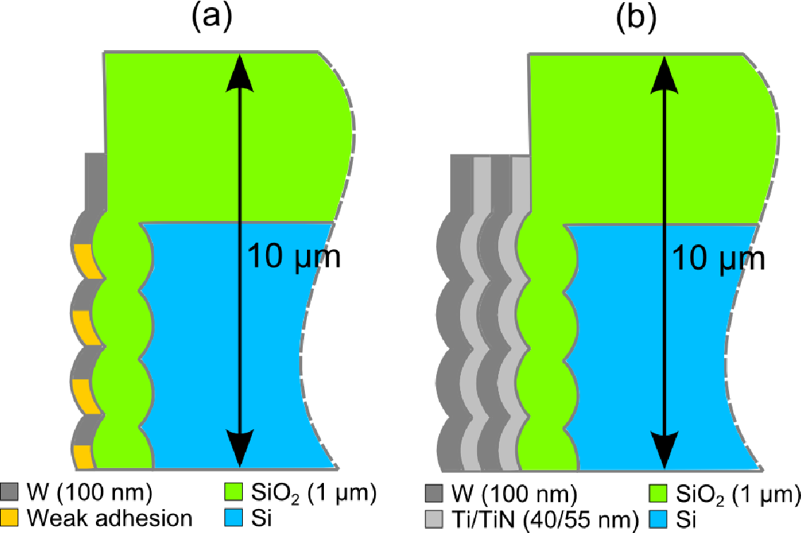
To explain the stress difference in the samples, the effects of the sidewall scallops on the vias
were studied. It is hypothesized that the scallops’ geometry causes the stress reduction. This
same interpretation was also mentioned by Krauss et al. Furthermore, a possible weak
adhesion of the scallops’ bottom due to shadowing effects was likewise investigated. This
phenomenon can lead to stress relaxation and can also further explain the difference
between the measurements.
A second structure with a double stack layer of W/TiN is considered in Krauss’s work. It is
probably employed in order to increase the TSV’s electrical conductivity without any
degradation of stress stability. This double stack structure is also considered here,
particularly due to the availability of experimental data for comparison.
To evaluate both hypotheses, mechanical simulations were performed on two structures as
depicted in Fig. 5.3.
For the simulation, an initial tensile residual stress was assumed on the tungsten
layers, as measured on the full-plate samples [85]. The material interfaces of the
scallops’ bottom were treated as a contact surface, thus the weak adhesion was
properly considered. The solution of the resulting surface problem is computed by
a combination of the Lagrange and the penalty method as described by Faraji
[87].