


Next: 6. Summary and Conclusions
Up: 5. Results
Previous: 5.2 High-Field Electron Transport
Subsections
5.3 Device Simulation
With the ever increasing costs of developing state-of-the-art microelectronic
technologies and devices, the optimization of semiconductor manufacturing
processes on a mere experimental basis is quite debatable. This entails the
employment of numerical tools which can simulate the behavior of these upcoming
technologies at different levels, such as fabrication (process simulation),
electrical characterization (device simulation) and integrated circuit (circuit
level). While a process simulator enables the simulation of implantation,
etching, diffusion, oxidation etc., the device simulator utilizes the
information from the process simulator for predicting the performance of the
devices in terms of current/voltage and capacitance/voltage
characteristics. Additionally, the device simulator can be used to extract
parameters as well as calibrate models for circuit simulation.
In this work, MINIMOS-NT [IuE04] has been used, which is a general-purpose
semiconductor device simulator that provides steady-state, transient, and
small-signal analysis of arbitrary two- and three-dimensional device
structures. The simulator is capable of dealing with different material systems
such as Si/Ge and group III/Vs compound semiconductors [Palankovski04] as well as
advanced device structures including SOI. The tool is equipped with a
comprehensive set of physically based models. As a part of this work, the
simulator has been extended to include the models that describe the effect of
strain on the electron mobility. The models are suitable for drift-diffusion
based device simulations.
5.3.1 Effective Mobility
For the evaluation of the effective mobility MOS structure were created with
uniform substrate doping concentrations ranging from  cm
cm to
to
 cm. The low-field mobility was calculated as described in
Section 4.5. Due to the quantum confinement of electrons,
the peak of the inversion layer concentration is not at the interface but is
slightly displaced. This effect leads to a decrease in the net inversion layer
capacitance, which reduces the drain current. To capture this phenomenon for
device simulation purposes efficiently two
approaches [van Dort94] [Jungemann01] have been suggested. In this
work, the approach based on modifying the conduction band edge through a
quantum corrected potential has been used [Jungemann01].
cm. The low-field mobility was calculated as described in
Section 4.5. Due to the quantum confinement of electrons,
the peak of the inversion layer concentration is not at the interface but is
slightly displaced. This effect leads to a decrease in the net inversion layer
capacitance, which reduces the drain current. To capture this phenomenon for
device simulation purposes efficiently two
approaches [van Dort94] [Jungemann01] have been suggested. In this
work, the approach based on modifying the conduction band edge through a
quantum corrected potential has been used [Jungemann01].
Fig 5.17a shows a comparison of the simulated effective mobilities
with the universal mobility curves obtained by Takagi [Takagi94]. The
parameter values used for the simulations are summarized in
Table 5.8. The results show a very good agreement between
the simulated and measured values. Fig. 5.17b shows the mobility
enhancement as obtained from (4.98). The model shows good agreement to
the strained mobility data obtained by Currie [Currie01] at MIT for the
case of biaxially strained Si grown on SiGe with 20% Ge content.
![\includegraphics[width=2.8in]{figures/rot_UnivMob-Uns.ps}](img944.png)
![\includegraphics[width=2.8in]{figures/rot_EEeff2025-new3.ps}](img945.png)

Figure 5.17:
Comparison of the effective mobility versus field for (a) unstrained
Si and (b) strained Si from the model and measurements reported from various
groups. MIT [Currie01], IBM [Rim02], Toshiba [Maeda03],
Hitachi [Sugii01], Stanford [Welser94a]
.
5.3.2 The dotFET Structure
The dotFET is a novel device concept proposed by Schmidt and
Eberl [Schmidt01] that utilizes the advantages of strain and SOI
technology and has the potential for enhancing device performance. Its
structure relies on the self-assembly of coherent, defect-free Ge dots on
Si. The Ge dots are grown in the Stranski-Krastanow [Stranski37] mode based
on interface thermodynamics, wherein a strained SiGe film grows
pseudomorphically up to a few monolayers followed by the formation of
three-dimensional islands. Depending on the growth conditions, the shape of
these islands can vary from pyramids, to truncated pyramids to huts and dome
shaped clusters. The SiGe dots are deposited on a pre-patterned (001) Si
substrate and have dimensions ranging from 100 to 300 nm. Next, a Si capping
layer is grown on top of the SiGe dot at low temperature, after which the
gate oxide is grown and the polysilicon gate formed. Due to the
three-dimensional nature of the dot, the strain in the capping layer is not
uniform but distributed with both uniaxial and shear components present. Then,
the Ge dot can be removed using selective wet chemical etching to leave a Si
free standing bridge, which forms the channel of the actual device
structure. To provide additional mechanical stability to the free standing
bridge, a nitride layer could be deposited before the SiGe dot removal. The
dotFET structure is shown in Fig. 5.18. This structure combines
potentially four advantages.
- The short channel behavior that hampers the off-state leakage current of
small devices is improved.
- The presence of strain in the Si layer increases the carrier mobility and
thereby reduces the delay time of the transistor.
- The Ge dots also offer the possibility of aligning themselves in stacks
on top of each other
to form a 3D stack. Therefore the area consumption is
less.
Figure 5.18:
Schematic cross section of the dotFET structure.
The performance of the dotFET is strongly dependent on the amount of strain
and its distribution within the Si capping layer. The strain state of the Si
depends on (i) growth conditions for the capping layer, (ii) size, shape and
composition of the Ge dots, (iii) material choice of the gate dielectric, (iv)
fabrication of source/drain junctions, (v) impact on the Si bridge during and
after the removal of the dot. The strain distribution can be determined either
by using experimental techniques such as X-ray diffraction or theoretically
from atomistic simulations using Tersoff potentials [Marchetti05] or finite
element calculation methods.
In this work, the strain distribution used was provided by University
Milano [Vastola] who have used an atomistic molecular dynamics code based
on the Tersoff [Tersoff89] interatomic potential for the
calculations. The code delivers the stress and strain tensor components at each
atomic site. From the complete data set a (010) plane passing through the
island apex is chosen. Fig. 5.19 shows the different
components of the strain tensor. The strain distribution is highly non-uniform
with large amount of strain present close to the Si/SiO interface.
The geometry of the dotFET device structure was created using the process
simulator Athena [ATHENA02]. A layer of Ge was grown on a uniformly doped Si
substrate and the Ge layer was etched to create a dome shape. A Si layer was
grown on top of this dome followed by an oxide layer. Next, a polysilicon gate
was formed and then source and drain implants were performed to obtain the
device structure. The diameter of the dome was kept to be 160 nm while the
thickness of the Si capping layer was 30nm. The structure was next modified to
keep/remove the Ge dot using the devEdit [Sil02] tool as well as to make
the device structure compatible for conversion to MINIMOS-NT format. After the
structure was converted from the .str (Athena) format to the .pif (MINIMOS-NT)
format, it was remeshed using the cgg tool [Cervenka99]. As a final step, a cut
(x-z plane) of the strain distribution was read into the device simulator
taking into account the proper scaling of the x and z coordinates. The
z-direction denotes the growth direction ([001]) whereas the x-direction is
along the channel. All the steps after the creation of the device structure
using Athena were automated through scripting. Fig. 5.20 shows the
final device structure with a substrate doping of
 and a 3
nm thick oxide layer. An additional threshold voltage adjust implant of
and a 3
nm thick oxide layer. An additional threshold voltage adjust implant of
 at 2.3 keV was performed.
![\includegraphics[width=2.5in]{figures/rot_Exx-pif.eps}](img949.png)
![\includegraphics[width=2.5in]{figures/rot_Eyy-pif.eps}](img950.png)
![\includegraphics[width=2.5in]{figures/rot_Ezz-pif.eps}](img951.png)
![\includegraphics[width=2.5in]{figures/rot_Exy-pif.eps}](img952.png)
![\includegraphics[width=2.5in]{figures/rot_Eyz-pif.eps}](img953.png)
![\includegraphics[width=2.5in]{figures/rot_Exz-pif.eps}](img954.png)
Figure 5.19:
Distribution of the strain tensor components as obtained from
atomistic growth simulations [Vastola].
Fig. 5.21 shows the distribution of the low-field mobility in the
unstrained and strained Si bridge. It can be clearly seen from
Fig. 5.21b that strain does increase the value of the low-field
mobility in the channel area. This enhancement of the mobility comes from the
significantly large ( ) values of the diagonal components of the strain
tensor existing in and around the channel region.
) values of the diagonal components of the strain
tensor existing in and around the channel region.
Figure 5.20:
The dotFET device structure used for simulation.
![\includegraphics[width=2.5in]{figures/rot_Mobility_uns2.eps}](img957.png)
![\includegraphics[width=2.5in]{figures/rot_Mobility_str2.eps}](img958.png)
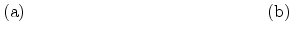
Figure 5.21:
Distribution of the mobility for an (a) unstrained and (b) a strained
Si bridge..
This mobility enhancement directly affects the transfer characteristics, as
shown in Fig. 5.22. A 37% and 43% enhancement in the drain current is
observed for the cases when the Ge dot is present and removed,
respectively. The threshold voltage of the device can be estimated to be 0.1 V.
Fig. 5.23 shows the output characteristics for two different values of
 . There is about 40% enhancement in the linear regime and more than 10%
enhancement in the saturation region, for both the cases where the Ge dot is
present and removed. It should be noted that the simulation results present an
optimistic scenario where in the strain values are large. However, depending on
the processing conditions, the final fabricated device structure may experience
some strain relaxation, thereby resulting in a reduced enhancement in the drain
currents.
. There is about 40% enhancement in the linear regime and more than 10%
enhancement in the saturation region, for both the cases where the Ge dot is
present and removed. It should be noted that the simulation results present an
optimistic scenario where in the strain values are large. However, depending on
the processing conditions, the final fabricated device structure may experience
some strain relaxation, thereby resulting in a reduced enhancement in the drain
currents.
Figure 5.22:
Simulated transfer characteristics of the dotFET.
Figure 5.23:
Simulated output characteristics of the dotFET.
Next: 6. Summary and Conclusions
Up: 5. Results
Previous: 5.2 High-Field Electron Transport
S. Dhar: Analytical Mobility Modeling for Strained Silicon-Based Devices
![\includegraphics[width=2.9in,angle=0]{figures/dotfet_freg2.eps}](img946.png)
![\includegraphics[width=3.0in]{figures/rot_DeviceDoping-pif3.eps}](img956.png)
![\includegraphics[width=2.7in]{figures/rot_Vts_all.eps}](img960.png)
![\includegraphics[width=2.7in]{figures/rot_IdVds_all.eps}](img961.png)