To allow an analysis of this subject,
the material equation (2.1)
and Poisson's equation
 |
(2.2) |
In an infinite crystal the ferroelectric polarization
![]() is uniform and
is uniform and
![]() , as in non-ferroelectric dielectrics. In finite
ferroelectrics, properties are more complicated. At the
surface
, as in non-ferroelectric dielectrics. In finite
ferroelectrics, properties are more complicated. At the
surface
![]() is reduced to zero, while in the
neighborhood of defects
is reduced to zero, while in the
neighborhood of defects
![]() does not vanish
and acts, according to (2.3), as the
source of an electric field, the so-called depolarization field.
does not vanish
and acts, according to (2.3), as the
source of an electric field, the so-called depolarization field.
The depolarization energy ![]() plays an important role in the
formation of the domains. When a crystal cools down from the
paraelectric phase in the absence of fields, there is, as outlined
previously, only a limited number of possible directions of the
spontaneous ferroelectric polarization. In order to minimize the free
energy, different regions polarize in one of those directions, thus
forming the domain structure. If no electric field is applied, this
structure usually shows no net polarization in a virgin
crystal.
plays an important role in the
formation of the domains. When a crystal cools down from the
paraelectric phase in the absence of fields, there is, as outlined
previously, only a limited number of possible directions of the
spontaneous ferroelectric polarization. In order to minimize the free
energy, different regions polarize in one of those directions, thus
forming the domain structure. If no electric field is applied, this
structure usually shows no net polarization in a virgin
crystal.
The other important contribution to the domain layout is the energy of
the domain walls ![]() . The final configuration will minimize the
sum of both of these entries to the total energy.
. The final configuration will minimize the
sum of both of these entries to the total energy.
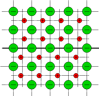
Basically two different types of domain walls are common in
ferroelectrics. The actual formation depends on the relative orientation of the
distortion direction of two neighboring domains with different
directions of the spontaneous polarization, the related angles being
![]() and
and ![]() , respectively. These two wall types are
outlined in Fig. 2.10. As the unit cell is not symmetric, the
, respectively. These two wall types are
outlined in Fig. 2.10. As the unit cell is not symmetric, the
![]() wall shows a distorted lattice structure. Furthermore, the
center ions can be located at two equivalent positions, thus
the respective figure shows two ions occupying the domain wall cells.
wall shows a distorted lattice structure. Furthermore, the
center ions can be located at two equivalent positions, thus
the respective figure shows two ions occupying the domain wall cells.
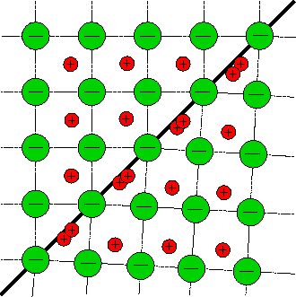
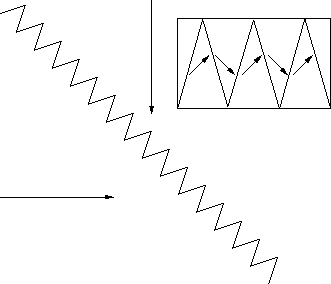
In principle also domain walls with a head to head scheme of
ferroelectric polarization are possible (Fig. 2.11), but as they
raise a large depolarization field, they are not favored in terms of
the energy. Head to head walls have been observed in
![]() , but electro-microscopic examinations revealed a
zigzagged domain wall layout (Fig. 2.12), which increased the
overall wall length by a factor of 5.
, but electro-microscopic examinations revealed a
zigzagged domain wall layout (Fig. 2.12), which increased the
overall wall length by a factor of 5.
In contrast to the magnetic equivalent, this field can be compensated by
the flow of free charge inside and outside the medium
 |
(2.4) |
 |
(2.5) |
Consequently, after the depolarization field is compensated by the free charges of a conductive ferroelectric material, theoretically a single domain structure should evolve. In reality, this is very unlikely since material properties are not ideal.