


Next: 3. Modeling of Hysteresis
Up: 2.4 Domains
Previous: 2.4 Domains
Contents
As a consequence of the above considerations, a domain configuration
evolves, which minimizes the total free energy  . The free energy
includes the two entries outlined above, the energy of the
depolarization field
. The free energy
includes the two entries outlined above, the energy of the
depolarization field  , stemming from the surface, and the energy
of the domain walls
, stemming from the surface, and the energy
of the domain walls  . With the energy term related to the shift
of the ions
. With the energy term related to the shift
of the ions
 , it finally reads as
 |
(2.6) |
The exact calculation of the energy term related to the dipoles,
, is far from trivial. A simplified model that allows
at least a rough analysis will be introduced later in Section 3.3.
The depolarization energy depends on the crystal and domain
geometry at the crystal surfaces. If the geometry is rather simple,
analytic calculations are possible, thus giving a good insight into
the mechanisms involved in the formation of domain structures. For
this consideration it is assumed that the currents inside the
ferroelectric material are neglectable and accordingly the surface
charge is not compensated.
In the simplest case of a thin crystal with uniform polarization
perpendicular to the surface, it is not surprising that the electric
depolarization field is proportional to the polarization [LG96]
 |
(2.7) |
Figure 2.13:
Periodic domain structure
|
|
Things get more complicated for multi domain structures. Still for a
periodic domain structure as outlined in Fig. 2.13 an analytic
description is possible. One obtains
 |
(2.8) |
for the depolarization energy, where  is the domain width,
 is the crystal thickness,
  is the polarization
in the center of a domain,
is the polarization
in the center of a domain,  is the crystal volume, and
  is a coefficient depending on the dielectric permittivity
[MF53]. Using the domain wall energy per unit area
is a coefficient depending on the dielectric permittivity
[MF53]. Using the domain wall energy per unit area
 , the overall domain energy in
Fig. 2.13 is
, the overall domain energy in
Fig. 2.13 is
 |
(2.9) |
The wall energy itself consists of several independent
contributions. These are the depolarization energy stemming from
 at the domain boundaries, the dipolar energy caused by
the misalignment of the ferroelectric dipoles on both sides of the
domain wall and the elastic energy.
at the domain boundaries, the dipolar energy caused by
the misalignment of the ferroelectric dipoles on both sides of the
domain wall and the elastic energy.
The minimum of these two entries is
 |
(2.10) |
and with respect to the domain width one reads
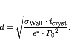 |
(2.11) |
Even this simple analysis delivers remarkable results. First, the
resulting domain width is finite if the polarization in the material
is not zero. This effect prevents any finite structure from showing a
uniform polarization. The next remarkable result is that neither the
energy of a domain wall nor the domain width can be zero. Finally,
this states that a pure random distribution of the orientations of the
dipoles is not possible, as the area between two of them already has
to be regarded as a domain wall. This leads to the strong result that
there have to be domains of finite size.
Next: 3. Modeling of Hysteresis
Up: 2.4 Domains
Previous: 2.4 Domains
Contents
Klaus Dragosits
2001-02-27
![\resizebox{\halflength}{!}{
\psfrag{t}{$t_\mathrm{cryst}$}
\psfrag{d}{$d$}
\includegraphics[width=\halflength]{figs/periodic.eps}
}](img144.gif)