Next: 5.2 Field Calculation over
Up: 5.1 Exposure Kinetics
Previous: 5.1.3 Modeling of Chemically
5.1.4 Simulation Flow
The preceding discussion shows that for conventional as well as for chemically
amplified resists the fundamental interaction between the resist material
and the exposing light is modeled by the simple first-order dissolution
laws of (5.12) and (5.15), i.e.,
 |
(5.18) |
Here the quantity
 (x;t) stands vicariously for the
PAC
m(x;t) and the PAG
g(x;t) depending on the
respective resist type.
The optical properties, e.g., the refractive index
n(x;t) of the
resist is determined by (5.3) and (5.8), which
combines to
(x;t) stands vicariously for the
PAC
m(x;t) and the PAG
g(x;t) depending on the
respective resist type.
The optical properties, e.g., the refractive index
n(x;t) of the
resist is determined by (5.3) and (5.8), which
combines to
 |
(5.19) |
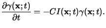
The two coupled equations (5.19) and (5.20) are
the central relations of the exposure/bleaching
module and were first proposed by
Frederick Dill and co-workers in his famous paper
series [135,74,140,141].
As can be seen from (5.19) the absorbed
light intensity
I(x;t) inside the optically nonlinear resist has to
be determined. Because the bleaching rate of
 (x;t) is almost
negligible when compared to the frequency of the EM field, the
refractive index
n(x;t) varies only
slowly with respect to the field propagation and thus a
quasi-static approximation can be applied to (5.19), i.e.,
(x;t) is almost
negligible when compared to the frequency of the EM field, the
refractive index
n(x;t) varies only
slowly with respect to the field propagation and thus a
quasi-static approximation can be applied to (5.19), i.e.,
 |
(5.20) |
For the same reason a steady-state field distribution can be assumed within
a time-step
tk t < tk + 1. Hence the time-dependence of the
EM field is a harmonic one and can be described most conveniently by a phasor
notation like
t < tk + 1. Hence the time-dependence of the
EM field is a harmonic one and can be described most conveniently by a phasor
notation like
![$\displaystyle \mathcal{E}(\mathbf{x};t)= \operatorname{Re}\!\left[\mathbf{E}_k(\mathbf{x})e^{-j\omega t}\right]\qquad\text{for}\qquad t_k\le t<t_{k+1}.$](img777.gif) |
(5.21) |
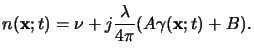
This means that the field phasor
Ek(x) for a certain
time-step tk has to be calculated in an inhomogeneous medium with a
spatially varying
permittivity
 (x;tk). The permittivity itself is related to the
refractive index by Maxwell's formula [11, p. 13],
(x;tk). The permittivity itself is related to the
refractive index by Maxwell's formula [11, p. 13],
 |
(5.22) |
Once the field phasor
Ek(x) is determined the absorbed
light intensity is easily calculated from it,
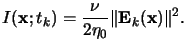 |
(5.23) |
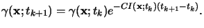
Now
I(x;tk) can simply be inserted into (5.21)
to obtain the chemical state
 (x;tk + 1) of the photoresist
for the next time step tk + 1.
(x;tk + 1) of the photoresist
for the next time step tk + 1.
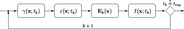
This procedure is graphically illustrated in the simulation flow of
Figure 5.1.
The crucial step throughout is the calculation of the EM field phasor
Ek(x) in (5.22).
Depending on the application, the required accuracy, and the dimensionality
of the simulation various methods exist. They range from simple vertical
scalar models to the physically most rigorous approach based on a direct
solution of the Maxwell equations. A survey over the most important simulation
methods is presented in the subsequent two sections, whereas in the next chapter
a newly developed rigorous three-dimensional approach is described.
Figure 5.1:
Simulation
flow of the exposure/bleaching module. The chemical state of the
photoresist is described by the concentration
 (x;tk) of
the PAC or PAG in case of a conventional or a chemically amplified
resist, respectively. The optical properties, e.g., the permittivity
(x;tk) of
the PAC or PAG in case of a conventional or a chemically amplified
resist, respectively. The optical properties, e.g., the permittivity
 (x;tk) of the resist depends on
 (x;tk).
Hence the EM field phasor
Ek(x) has to be
calculated inside an inhomogeneous medium. With the absorbed light
intensity
I(x;tk) the concentration
(x;tk).
Hence the EM field phasor
Ek(x) has to be
calculated inside an inhomogeneous medium. With the absorbed light
intensity
I(x;tk) the concentration
 (x;tk + 1) for the next time-step tk + 1 can
be derived.
(x;tk + 1) for the next time-step tk + 1 can
be derived.
|
|
Before we begin with the discussion of field calculation, we want to point out
an important property of the quasi-static approximation applied above.
Principally the resist is an optically nonlinear medium.
Because of the different time constants,
i.e., the field varies much faster than the chemical processes occur,
the dissolution law (5.19) can be explicitly discretized with
respect to time (cf. (5.21)) and the
time-dependence of the field can be assumed to be a harmonic one
(cf. (5.22)). Hence the nonlinear time-varying
problem is transformed to a series of inhomogeneous linear steady-state
problems.
Next: 5.2 Field Calculation over
Up: 5.1 Exposure Kinetics
Previous: 5.1.3 Modeling of Chemically
Heinrich Kirchauer, Institute for Microelectronics, TU Vienna
1998-04-17