There are levels of integration differentiated by the status of the semiconductor process flow.
![\includegraphics[width=1.9\textwidth,clip=true]{figures/development_flow.rot.ps}](img185.png)
|
By standardizing the flow description information for this stage, it is possible to define an automated converter which transfers the information identified in Section 4.2.2 into the abstracted semiconductor process simulator input language called SPR (Simple Process Representation) which is the input language for the commercial tool LIGAMENT. This tool generates the final process simulator input command files. This task is implemented via PERL-converter scripts. By using the SPR language it is possible to use various different process simulators even from different vendors like DIOS or SUPREM4.
Once the semiconductor process flow is frozen and released, the MES system provides any input on the process flow which is necessary for process simulation. However this information must be reduced to the subset relevant for process simulation. This task is again performed with PERL-converter scripts and results in the table shown in Figure 5.1.
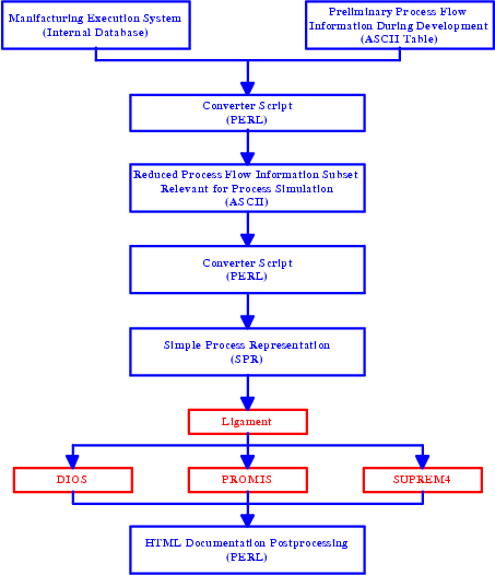
The overall scheme of conversion is outlined in Figure 5.2.
Two different data sources have been established for process flow conversion. First the MES database and second a simple ASCII table representation. Both sources are converted into a common reduced process flow information subset suitable to get a good, compact overview of the relevant process flow information. A second converter script is transferring this information into the simple process representation syntax as input to the TCAD framework tool LIGAMENT. This tool is able to generate different types of process simulator (e.g. DIOS or TSUPREM4) command files. After a full process flow simulation was performed the resulting structural and doping information can be used to generate a HTML documentation of every simulated process step.
One of the most important information to be provided to the process simulator in detail are the diffusion and oxidation recipes. These recipes are normally not stored in the MES but in a local diffusion furnace database. An example for such a system is the Supervisor Station from ASM. These systems have an internal format representation which has to be converted into a meta-syntax including the relevant information for the process simulator. An example of the original format of such a diffusion recipe is given in Listing 5.1. The listing shows the typical level of detail of a diffusion program. The program includes the analog output level and the alarm limits of the gas flow controllers, alarm patterns of the digital input channels and temperature and time settings of the diffusion program.
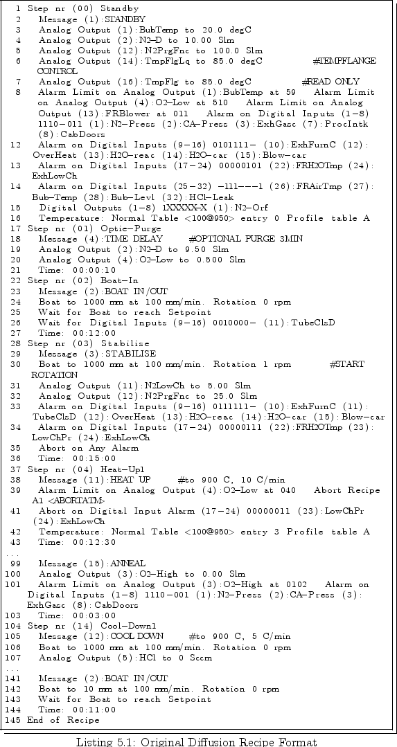
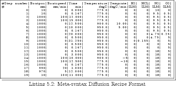
The compressed representation of the program shown in
Listing 5.1 is obtained by the diffusion recipe converter
as given in Listing 5.2 in the meta-syntax format.
The first column gives the step number, the second the position of the quartz
boat with the wafers. The third column shows the boat speed indicating how
fast the boat is moved into and out of the quartz tube in the furnace. The
next column shows the duration of the step. The following two columns give the
target temperature and if the temperature has to be ramped with a certain ramp
rate over the duration of the step. Finally the remaining rows give the
targets for the gas flows set during the diffusion step.
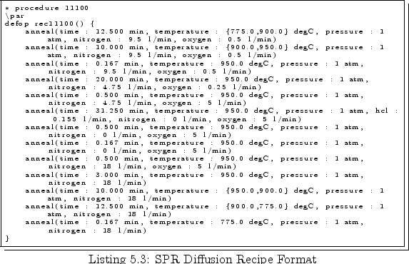
The final simulator diffusion program is obtained by the meta-syntax to
SPR converter as shown in Listing 5.3. This syntax is already
very close to the process simulator syntax. However it does not include
special model commands, specific to the process simulator. The syntax is
targeted to give the generic inputs similar to every process
simulator. Specific process simulator commands have to be defined with
include statements.
The final simulator syntax is then generated by the TCAD environment.
The conversion of the other recipes (implantation, etching and deposition) is quite straightforward. For implantation the database contains exactly the same information as needed by the process simulator. For isotropic etching and deposition only the etch rates and time are needed to simulate the change of geometry. The only not well developed interface is the anisotropic etch interface because of the unavailability of reliable and fast process simulators for this step. The equipment simulators needed for simulation of the effects of changes in the dry etch recipes on the overall etch profiles are still not available for routinely simulation tasks.
Because of the established system the turnaround time for setting up a process
simulation flow has been reduced from days to hours. The probability of faults
in the first setup of the process flow has been dramatically
reduced. Especially the diffusion recipe conversion is inevitable to guarantee
that a possible mismatch between simulation and measurements is not due to a
wrong entered simulation recipe but because of poor calibration or new effects
not covered by simulation.