Previous: 4.1.3.1 BV of P-SOI LDMOSFETs Up: 4.1.3 Simulation Results Next: 4.2 Lateral Trench Gate SOI-LDMOSFETs
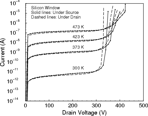
Figure 4.7 shows the leakage currents of P-SOI LDMOSFETs versus drain voltage
as a function of the lattice temperature. The leakage current increases nearly
exponentially with increasing temperature [59,103,104], because the carrier
generation rate follows the intrinsic carrier concentration
![]() . The shape of the
leakage current does not change significantly with temperature, but the
BV increases. The increase of BV is caused by
the reduction of the mean free path of the carriers due to lattice scattering,
requiring a higher field to initiate impact ionization.
. The shape of the
leakage current does not change significantly with temperature, but the
BV increases. The increase of BV is caused by
the reduction of the mean free path of the carriers due to lattice scattering,
requiring a higher field to initiate impact ionization.
Generally, there are two components - a space charge generation current and a diffusion leakage current - responsible for the leakage current under reverse bias conditions. The diffusion leakage current will decrease with increased doping concentration. As shown in Figure 4.2 and Figure 4.3, the depletion layer widths of the P-SOI LDMOSFETs are almost the same. In the P-SOI with a silicon window under the drain, a higher substrate doping concentration was used to obtain the maximum BV. Therefore, a lower leakage current (Figure 4.7) is obtained compared to that in the P-SOI with a silicon window under the source.
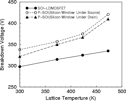
As shown in Figure 4.8, the breakdown voltage gives a similar temperature dependence as conventional SOI-LDMOSFETs but for P-SOI LDMOSFETs the slope is somewhat larger. This means that BV characteristics of P-SOI LDMOSFETs are between SOI and junction isolated devices.
The temperature distribution inside a device due to self-heating is determined
by the heat generation profile and the thermal conduction inside SOI
LDMOSFETs [142,143]. In majority carrier devices such as MOSFETs, there is
very little carrier recombination and as a result heat generation is mainly
caused by Joule heating. This effect can be seen in SOI LDMOSFETs. The Joule
heating is proportional to the local resistances of the ![]() -drift and channel region.
-drift and channel region.
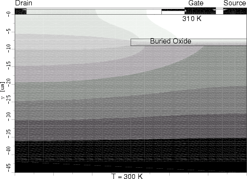
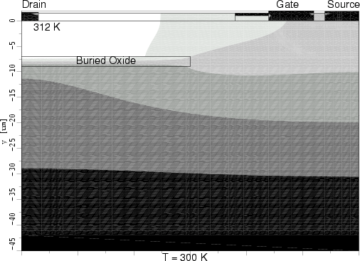
Figure 4.9 and Figure 4.10 show the temperature distributions inside the
P-SOI LDMOSFETs with an applied gate voltage
![]() of 15V and a drain-source
voltage
of 15V and a drain-source
voltage
![]() of 10V. The bottom of the devices is assumed to be isothermal
at 300 K. To reduce the simulation time, a substrate thickness of 36
of 10V. The bottom of the devices is assumed to be isothermal
at 300 K. To reduce the simulation time, a substrate thickness of 36![]() m is
used. In these structures the silicon window acts as a good thermal
conductor.
m is
used. In these structures the silicon window acts as a good thermal
conductor.
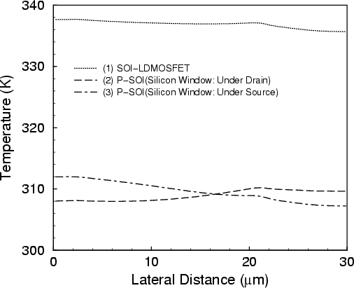
In the P-SOI LDMOSFET with the silicon window under the drain, the temperature rise is highest in the gate region (310K, white region in the figure) and decreases towards drain (308K) as shown in Figure 4.9. In the case of the P-SOI LDMOSFET with the silicon window under the source, the temperature rise is highest in the drain region (312K) of the drift layer and decreases towards gate and source (307K) as shown in Figure 4.10.
Figure 4.11 gives a comparison of the temperature versus lateral distance under the surface for conventional SOI-LDMOSFETs and P-SOI LDMOSFETs. This figure shows that the silicon window in the P-SOI drastically reduces the temperature rise due to self-heating.
Jong-Mun Park 2004-10-28