


Next: 2.9 Co Tunneling
Up: 2 Theory of Single
Previous: 2.7 The Double Tunnel
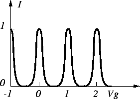
Adding to the double tunnel junction a gate electrode Vg which is
capacitively coupled to the island, and with which the current flow can be
controlled, a so-called SET transistor is obtained
(see Fig. 2.12).
Figure 2.12:
SET transistor.
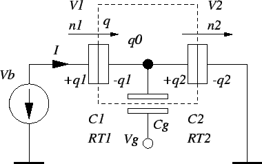 |
The first experimental SET transistors were fabricated by T. Fulton and
G. Dolan [35] and L. Kuzmin and K. Likharev [71]
already in 1987. The effect of the gate electrode is that the
background charge q0
can be changed at will, because the gate
additionally polarizes the island, so that the island charge becomes

The formulas derived in Section 2.7 for the double junction
can be modified to describe the SET transistor. Substituting
 in (2.33), the new
voltages across the junctions are
in (2.33), the new
voltages across the junctions are
with
 .
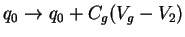
The electrostatic energy has to include also
the energy stored in the gate capacitor, and the work done by the gate voltage
has to be accounted for in the free energy. The change in
free energy after a
tunnel event in junctions one and two becomes
.
The electrostatic energy has to include also
the energy stored in the gate capacitor, and the work done by the gate voltage
has to be accounted for in the free energy. The change in
free energy after a
tunnel event in junctions one and two becomes
At zero temperature only transitions with a negative change in free energy,
 or
or
 ,
are allowed. These conditions may be used
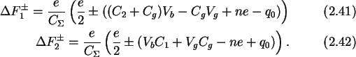
to generate a stability plot in the Vb-Vg plane, as shown in
Fig. 2.13.
,
are allowed. These conditions may be used
to generate a stability plot in the Vb-Vg plane, as shown in
Fig. 2.13.
Figure 2.13:
Stability plot for the SET transistor. The shaded regions are
stable regions.
 |
The shaded regions correspond to stable regions with an integer number of
excess
electrons on the island, neglecting any non-zero
background charge. If the
gate voltage is increased, and the bias voltage is kept constant
below the Coulomb blockade,
 ,
which is equivalent to a cut through the
stable regions in the stability plot, parallel to the x-axis,
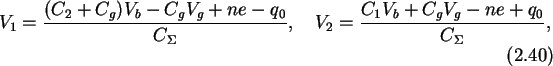
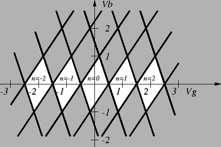
the current will oscillate with a period of e/Cg.
As opposed to the Coulomb oscillations in a single junction,
which were explained
in the introduction1, where the periodicity in
time of discrete tunnel events is observed, these are Coulomb oscillations which have a
periodicity in an applied voltage, where regions of suppressed tunneling and
space correlated tunneling alternate.
Fig. 2.14 shows the
qualitative shape of the current oscillations.
,
which is equivalent to a cut through the
stable regions in the stability plot, parallel to the x-axis,
the current will oscillate with a period of e/Cg.
As opposed to the Coulomb oscillations in a single junction,
which were explained
in the introduction1, where the periodicity in
time of discrete tunnel events is observed, these are Coulomb oscillations which have a
periodicity in an applied voltage, where regions of suppressed tunneling and
space correlated tunneling alternate.
Fig. 2.14 shows the
qualitative shape of the current oscillations.
Figure 2.14:
Coulomb oscillations in a SET transistor.
 |
Increasing the bias voltage
will increase the line-width of the oscillations, because the regions where
current is allowed to flow grow at the expense of the remaining Coulomb blockade
region. Thermal broadening at higher temperatures or a
discrete energy spectrum
change the form of the oscillations considerably. Coulomb oscillations have been
theoretically investigated by C. Beenakker [15].
Next: 2.9 Co Tunneling
Up: 2 Theory of Single
Previous: 2.7 The Double Tunnel
Christoph Wasshuber