

Next: Voltage-Controlled Voltage Sources
Up: 3.1 Free Energy of
Previous: 3.1.1 Notation
Using the capacitance matrix, charges and
potentials are related by

The sub-matrices
Ca,
Cb, and
Cc have dimensions
 ,
,
 ,
and
,
and
 respectively. The capacitance matrix is a symmetric matrix, which allows
efficient storage and handling. Consequently
Ca and
Cc are
symmetric.
The unknown quantities of charges on potential-nodes and floating-nodes and potentials of
charge-nodes,
 ,
can be written in terms of the known
quantities which are the potentials on potential-nodes and floating-nodes and the charges on
charge-nodes.

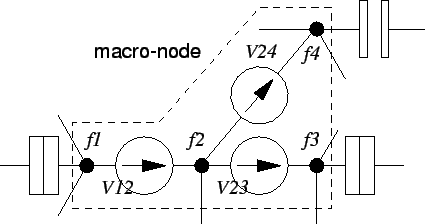
The
potentials of the floating-nodes must be derived from the equations of the macro-nodes,
which are the known sum of charge of each macro-node, and the individual potential
differences given by the voltage sources comprising a macro-node. An example of a
macro-node is shown in Fig. 3.2.
Figure 3.2:
A macro-node is formed by a set of voltage sources which are not connected
to ground.
 |
The voltage sources give a set of Nfm-1
equations, where Nfm is the number
of nodes in a macro-node, which are for the example
of Fig. 3.2

Voltage sources must not be short circuited. That is,
no loop consisting
solely of voltage sources may exist in the circuit.
With the additional equation for the charge of the macro-node

which is taken from (3.2) by adding all Nfm lines for the node
charges comprising one macro-node, one has
Nfm equations for the potentials of the Nfm floating-nodes.
The electrostatic energy of a circuit can be expressed using the relation
which links known charges and potentials with the unknown quantities,
(3.2), as, (see also (2.5))


Next: Voltage-Controlled Voltage Sources
Up: 3.1 Free Energy of
Previous: 3.1.1 Notation
Christoph Wasshuber


