


Next: 5.2.7 Multi Tunnel Junction
Up: 5.2 Single Electron Memories
Previous: 5.2.5 Manufacturability
One design possibility is to mimic conventional CMOS architecture with SET
devices [103]. Two static SET memory cell designs or flip-flops
based on this approach were proposed by A. Korotkov et al. [66]
(see Figs. 5.6 and 5.7).
Figure 5.6:
Circuit diagram of a SET static memory cell (flip-flop).
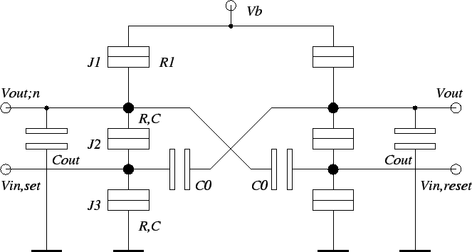 |
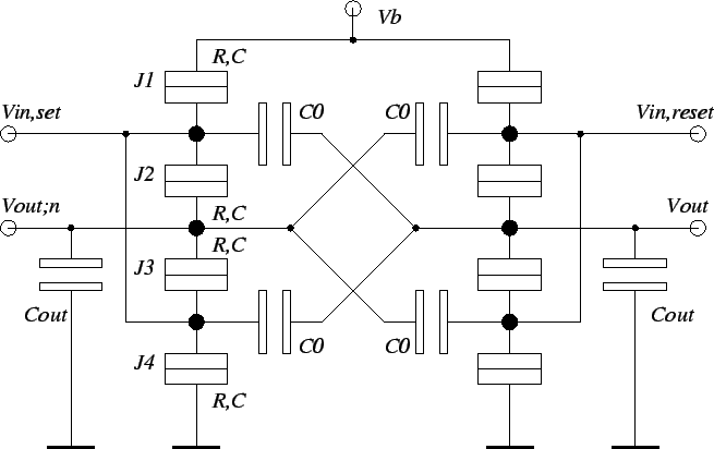
Figure 5.7:
Circuit diagram of a complementary SET static memory cell
(flip-flop).
 |
Junctions J2 and J3 form a SET transistor, J1: R1 is the load
resistance.
 ,
the load capacitor, is much bigger than the
tunnel junction capacitance C, which means that
,
the load capacitor, is much bigger than the
tunnel junction capacitance C, which means that
 electrons
represent one bit of information. A large
suppresses shot
and thermal noise. Co-tunneling is in circuits built from SET transistors less
important, since a logic state is represented by more than one electron.
On the contrary, SET logic families which code digital information by
single electrons, such as the multi-tunnel-junction memory
(Section 5.2.7) and ring memory (Section 5.2.8), are prone to
errors caused by co-tunneling. The 'complementary' flip-flop of
Fig. 5.7 replaces the load tunnel junction with another SET
transistor, which makes it slightly more complex, but all its tunnel
junctions are similar.
electrons
represent one bit of information. A large
suppresses shot
and thermal noise. Co-tunneling is in circuits built from SET transistors less
important, since a logic state is represented by more than one electron.
On the contrary, SET logic families which code digital information by
single electrons, such as the multi-tunnel-junction memory
(Section 5.2.7) and ring memory (Section 5.2.8), are prone to
errors caused by co-tunneling. The 'complementary' flip-flop of
Fig. 5.7 replaces the load tunnel junction with another SET
transistor, which makes it slightly more complex, but all its tunnel
junctions are similar.
Next: 5.2.7 Multi Tunnel Junction
Up: 5.2 Single Electron Memories
Previous: 5.2.5 Manufacturability
Christoph Wasshuber