3.2 I/O layer
The I/O layer presents an abstraction scheme used to read persistent
Wafers into the core data structures. These data are then available to all
tools integrated with the WAFER-STATE-SERVER. The concept of this layer allows for an
arbitrary number of file formats to be supported. Thereby the problem of
reading and writing data from or to different files is solved.
The I/O module is split into two parts, the Reader
and the Writer. Each part consists of several C++ interface classes that
are used to traverse the data. The implementation of these classes takes care to
handle data transfer to or from the underlying file or database3.1.
For each file format to be supported all these interface classes must be
implemented. The classes for Reader and Writer are completely independent
from each other. Thus, only the set corresponding to the required operation
(reading or writing) for a certain file format must be implemented.
The I/O layer is also used in a tool supplied with the WAFER-STATE-SERVER
to convert between all supported file formats (ioconv). This program
simply connects a Reader and a Writer object. The type of the input and
output file format is thereby selectable at runtime. We succeeded to keep the
Reader and Writer APIs rather compact which is best illustrated by the
fact that this conversion tool was realized with less than  lines of C++
code. (c. f. Appendix A).
lines of C++
code. (c. f. Appendix A).
Apart from a pure file conversion the I/O layer serves
an additional purpose. As pointed out earlier some file formats semantically
differ from the data standard as it is defined in the WAFER-STATE-SERVER data model. The
implementation of the I/O module for such file formats must also take care
of these differences. If, for example, a certain file format is capable of
storing several element types (as with the DF-ISE file format), then the
Reader implementation must take care of delivering only tetrahedrons to the
WAFER-STATE-SERVER. If a file format supports only boundary conforming meshes (DF-ISE)
then the Writer implementation must take care to make boundary conforming
grids before data are actually stored on the file.
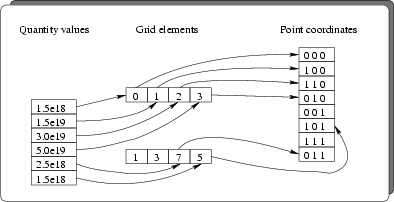
Data are organized in several
sections. Care was taken to avoid the storage of redundant
information. Therefore, a global point list was used to store the point
coordinates of all grids of the Wafer. A grid is realized as a set of grid
elements, each with either 2 (one-dimensional grid), 3 (two-dimensional
triangular grid), or 4 (three-dimensional tetrahedral grid) references into the
point list. A grid has an associated name which is used to reference the grid
from a quantity. A quantity is realized as a list of abstract
values3.2 and a grid
reference. Fig. 3.2 depicts how the values of a quantity are associated
with the coordinates of the according point.
Figure 3.2:
Relation
between quantity values, grid elements and point coordinates. The sequence of
the data in the value list corresponds to the ordering of the point references
in the grid element list.
 |
Properties are realized as attributes with only one (abstract) value that
do not reference a grid. Properties are defined on the whole segment, and are
used to store attributes that are constant over the whole segment (e.g. the
material type of a segment).
There exist also grids that are not referenced from any quantity.
These so-called stand-alone grids are optional, and are only necessary to define
the geometry of a segment in case no attributes are present. Thus, a
stand-alone grid is used to define the geometry of a Wafer without any
impurity descriptions or other quantities.
Boundaries
contain attributes, used to store quantities on an interface between two
segments. Boundaries are defined in the Boundaries section of the
segment. From the data structure point of view they are similar
to segments except for the dimension of the grid elements which is one less
than the elements in the segments section.
Fig. 3.3 depicts the algorithm to read data
from a persistent
Figure 3.3:
I/O reading
algorithm.
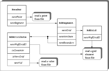 |
Wafer. The data are read hierarchically.
All methods named next... are iterators (c. f. Appendix A.4) over
the contents of a section. They return an instance of an object or indicate the
end of a section. The sequence of the method calls is mandatory and must occur
as described below.
- An object of type Reader must be instantiated. This can either be
done by directly invoking the constructor of a certain Reader
implementation or via the dynamic instantiation method
(c. f. Appendix A.1). The dynamic instantiation method is preferred
since it hides all details of the Reader implementation from the
application code3.3.
- As a first step all points must be retrieved. This is achieved by a call
to the nextPoint method of the Reader class. The method returns
either a point or indicates "end-of-section" after the last point was read.
- Now the segments must be retrieved. This is done via an interface of
type RdSegment. The nextSegment method returns an object of this
type or indicates "end-of-section" after the last segment was
retrieved. For each segment the following sequence is used to get the data.
- The method nextGrid of the RdSegment class returns an
object of type RdGrid for each stand-alone grid that is stored on a
file. The grid elements are fetched from the RdGrid interface with
calls to the nextWafGridEl method.
- After the last stand-alone grid was fetched the attributes must be
fetched. This is done by calling the nextAttribute method of the
RdSegment interface once for each attribute. The method returns an
object of type RdAttribute. The end of the attributes is again
indicated as described above. The RdAttribute interface contains the
following three methods.
- isConstAttr is used to determine whether the attribute is a
quantity (false) or a property (true).
- nextWafGridEl does exactly the same as in the RdGrid
interface. Note that this method must only be invoked for quantities, but
not for properties. Grids can be shared by several attributes. For
performance reasons it was chosen that the grid is read only the very
first time an attribute references it. If a grid is tried to be read the
second time an error condition is indicated. The predicate
isNewGrid of the RdAttribute class returns true for
the first occurrence of a grid and false otherwise.
- nextVal returns an instance of an abstract value.
- After the attributes the boundaries must be fetched in a way similar
to attributes. From a data structure point of view a boundary is identical to an
attribute3.4.
Fig. 3.4 depicts the algorithm to write data to a file.
Figure 3.4:
I/O writing
algorithm.
 |
The Writer interface works similar to the Reader. Again the order of the
method calls is mandatory and must not be altered. Additionally to the classes
that directly correspond to the respective classes in the Reader interface
there are extra classes used to help in syntactically closing a section of the
file. The destructor of these classes is reserved to perform that task.
- An object of type Writer must be instantiated. This can either be
done by directly invoking the constructor of a certain Writer
implementation or via the dynamic instantiation method
(c. f. Appendix A.2). The dynamic instantiation method is preferred for
the same reasons as with the instantiation of the Reader.
- The method openPoints of the Writer interface must be
called to initiate the transfer of points. The method returns an object of
type WrPoints. The nextPoint method of WrPoints must be
called once for each point. The points are orderer in the way they are written
to the file, starting with index 0 for the first point. After the last point
the points section must be closed by explicitly assigning a 0
handle3.5 to the WrPoints section.
- After the points are written and the points section is properly closed
the segments need to be transferred. This is initiated by a call to the
openSegments method of the Writer class. This method returns an
object of type WrSegSection which in turn contains a method to open a
segment section (nextSegment. The WrSegment interface
contains three methods to write stand-alone grids (nextGrid) to open the
attributes section (openAttributes) and to open the boundaries section
(openBoundaries). A segment must be created in the following manner.
- All stand-alone grids must be written first. To start writing a
stand-alone grid the method
nextGrid must be invoked. It
returns an object of type WrGrid. The method nextEl of the
WrGrid interface must be called for each grid element that is to be
stored on a file. Note that the the elements are again ordered the way they
are written, starting with index 0. After the last element was transferred
the WrGrid section must be closed by an explicit assignment to a 0
handle.
- The method openAttributes must be used to open the attributes
section of that segment. It returns an object of type WrAttributes
which contains methods to dump an attribute. The write cycle of an attribute
depends on whether a quantity or a property is to be written. For quantities
a grid that holds the quantity's values is to be dumped first. This is done
in the very same way as for stand-alone grids described above
(nextGrid. The actual values of the attribute are then written via an
object of type WrAttribute that is returned from the
nextAttribute method of the WrAttributes interface. The
nextVal method is invoked once for each value that is to be
stored. For properties this method must only be invoked once. After
completion of a WrAttribute it must be closed. After the last
attribute was written the WrAttributes section must be closed.
- The method openBoundaries opens the boundaries section and
returns an object of type WrBoundaries. Note that a call of this
method is optional since boundaries are only contained optionally. The
WrBoundaries object contains the method nextGrid that must be
used exactly the same was as for stand-alone grids and for attributes. Since
from a data structurepoint of view boundaries are identical to attributes, the
method nextBoundary returns an object of type WrAttribute. The
method nextVal of that object is again used to store an abstract
value on the file.
- A finished segment must be closed by assigning a 0 to the
WrSegment object. After the last segment was written also the
WrSegSection must be closed.
- As a final step the Writer object itself must be closed.
The Reader interface contains methods that are
used to query the name of segments, attributes and grids, and to query the
name of the grid reference of an attribute. Fig. 3.5 and
Fig. 3.6 depict a class diagram of the Reader and Writer
processes respectively, in the UML (UNIFIED MODELING LANGUAGE) notation. The
figures show all classes involved in the reading and writing process. An
implementation of a Reader or Writer must inherit all depicted classes and
implement the specified (virtual) methods.
Figure 3.5:
UML reading class diagram.
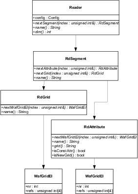 |
Figure 3.6:
UML writing class diagram.
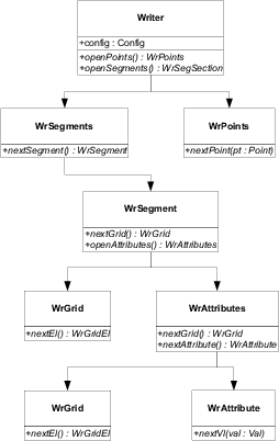 |
Subsections
2003-03-27