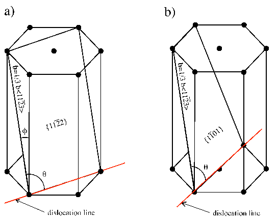
| Figure 4.4: | The two most favorable slip systems in the systems AlxGa1-xN/GaN and InxGa1-xN/GaN: a) ⟨113⟩{112} observed by Srinivasan [71] and b) ⟨113⟩{101} determined by Jahnen [33]. |
Steeds developed a procedure to calculate the energy of one infinite straight dislocation in the bulk of an infinite material [72], which is considered anisotropic with a certain crystallographic symmetry. The result for the hexagonal symmetry is briefly described in [28].
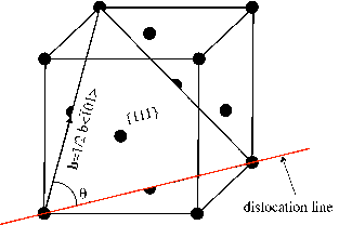
Here, this treatment is adopted in order to calculate the energy (with and without the contribution of the dislocation core, see Chapter 3.2) for a dislocation whose slip system is 1∕3⟨113⟩{112} or 1∕3⟨113⟩{101} in Al0.2Ga0.8N and in In0.2Ga0.8N (see Figure 4.4). The same treatment with the appropriate elastic constants is used to calculate the energy for the so called 60∘ dislocation slip system ⟨110⟩{111} in Si 0.8Ge0.2 (see Figure 4.5).
| Figure 4.4: | The two most favorable slip systems in the systems AlxGa1-xN/GaN and InxGa1-xN/GaN: a) ⟨113⟩{112} observed by Srinivasan [71] and b) ⟨113⟩{101} determined by Jahnen [33]. |
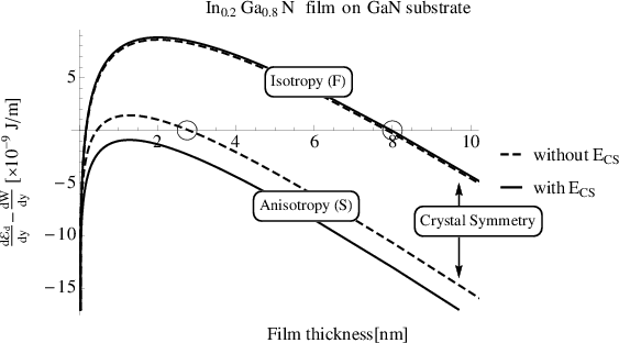
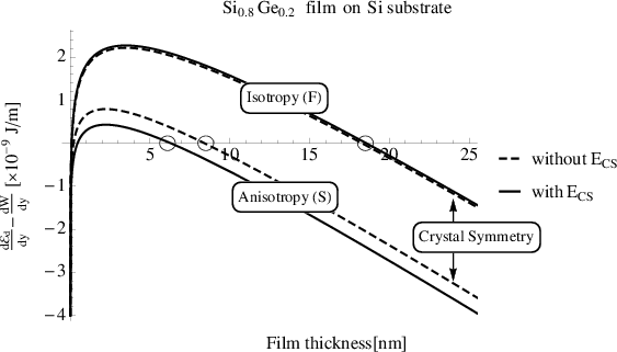
In the following, the difference between the dislocation energy d d∕dy and the work
d
d∕dy and the work
d ∕dy done by the misfit stress field for each alloy is discussed. When the resulting value is
positive, fully coherent accommodation of the misfit strain is energetically preferred, while
for negative values introduction of misfit dislocations becomes favored. The highest film
thickness yielding the difference of 0 indicates the equilibrium critical thickness . The
resulting values for the three different alloys as a function of the film thickness are plotted in
Figures 4.6, 4.7, and 4.8. Each figure has two sets of curves, one for the Freund,(isotropic
elasticity) and one for the Steeds (anisotropic elasticity) procedure. For all systems
investigated here, the anisotropy lowers the critical thickness . Additionally, it turns out
that the inclusion of the integral along the core surface S3 (values labelled “with
Ecs” in the figures. For the description of Ecs see Section 3.2) has in all cases
only a negligible impact (or at least on order of magnitude smaller effect than
the correct crystal symmetry) on the predicted critical thickness (see Table 4.2).
∕dy done by the misfit stress field for each alloy is discussed. When the resulting value is
positive, fully coherent accommodation of the misfit strain is energetically preferred, while
for negative values introduction of misfit dislocations becomes favored. The highest film
thickness yielding the difference of 0 indicates the equilibrium critical thickness . The
resulting values for the three different alloys as a function of the film thickness are plotted in
Figures 4.6, 4.7, and 4.8. Each figure has two sets of curves, one for the Freund,(isotropic
elasticity) and one for the Steeds (anisotropic elasticity) procedure. For all systems
investigated here, the anisotropy lowers the critical thickness . Additionally, it turns out
that the inclusion of the integral along the core surface S3 (values labelled “with
Ecs” in the figures. For the description of Ecs see Section 3.2) has in all cases
only a negligible impact (or at least on order of magnitude smaller effect than
the correct crystal symmetry) on the predicted critical thickness (see Table 4.2).
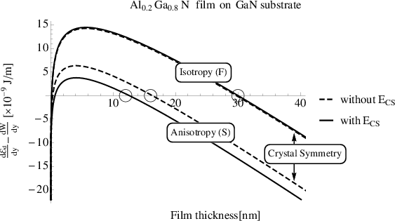
| Figure 4.6: | dd∕dy -d∕dy as function of the Al0.2Ga0.8N film thickness. dd∕dy is
calculated assuming isotropic (Freund model (F)) and anisotropic (Steeds model (S))
elasticity, with or without the evaluation of the integral along the core surface Ecs.
d∕dy is calculated according to equation (4.9). The critical thickness values of an
Al0.2Ga0.8N film grown on a GaN substrate are indicated by a circle. |