4 Coarse-Grained Shared-Memory Parallel Mesh Adaptation
The increased popularity of computational investigations in science and engineering utilizing PDEs has lead to a wide variety of methods and techniques based on FEMs or FVMs for numerically solving various problems [47], [130], [131], [132], [133], [134], [135], [136], [137]. Besides the mathematical basis modeled with PDEs every simulation requires a dedicated simulation domain on which these PDEs are solved, constrained by the applied boundary conditions. FEMs and FVMs require this physical domain to be discretized into a mesh, a step known as mesh generation. In order to generate this mesh numerous algorithms and methods have been developed, e.g., advancing front methods as implemented in NETGEN [138], [139] or by Löhner [140], incremental algorithms [49], and edge-flipping algorithms [49], [57], [141], [142]. However, the numerical results of a simulation depend on the resolution and quality of the underlying discretization, i.e., the mesh, which, among other areas, is particularly important for TCAD simulations (see Chapter 1). For example, the robustness of the solution process and the accuracy of calculating charge carrier distributions in a discretized transistor device is influenced by the quality of the provided mesh.
Mesh adaptation is an important method to improve the quality of an initially generated mesh. This method can be applied both locally and globally, depending on the specific regions of interest. However, considering an entire simulation workflow (e.g., repeated simulations due to parameter variability studies) the mesh adaptation step can pose a serious computational bottleneck. Various methods and approaches were invented in the past to accelerate the meshing step with a particular focus on distributed-memory systems. However, since in modern computer systems the number of available cores on each node is steadily increasing [143], mesh adaptation procedures need to be tailored to these highly parallel, shared-memory computing platforms for maximizing efficiency. Hence, shared-memory as well as hybrid mesh adaptation approaches were developed [29], [30], [31]. Nevertheless, mesh adaptation is an inherently memory bound problem limiting obtainable speedups [144]. This is due to the fact the mesh adaptation operations, such as vertex insertion or edge splitting, require random memory access patterns in order to update the adapted mesh data structures.
However, shared-memory mesh adaptation methods often utilize a so-called fine-grained approach [145], where the parallelization stems from the mesh adaptation process itself, e.g., a parallel edge splitting algorithm. Hence, most of the applied mesh adaptation processes in fine-grained approaches are specifically tailored to the provided data structure. This often hinders or even prevents the integration of already available highly-tuned and well-tested serial mesh adaptation routines. In order to overcome this challenge one approach is to decompose the initial mesh into several partitions, which are subsequently adapted in parallel using such available serial mesh adaptation methods, i.e., following a coarse-grained parallelization approach [145]. Here, the parallelization stems from the simultaneous adaptation of different partitions using a serial algorithm. However, to guarantee a safe parallel execution of the adaptation process (i.e., preventing data races or race conditions on the interfaces of adjacent partitions), graph coloring algorithms (see Chapter 3) can be utilized to bin the partitions into independent sets. Additionally, it is important to design a strategy how the interfaces of adjacent partitions have to be handled to obtain a conforming mesh without jeopardizing the mesh element quality.
Therefore, in the following, a novel coarse-grained shared-memory parallel mesh adaptation framework (also referred to as coarse-grained mesher) is presented focusing particularly on tackling the aforementioned challenges [18], [31]. The main idea behind the presented framework is the partitioning of an initial mesh into independent sets of partitions, created by the graph coloring algorithms introduced in Chapter 3. The members of these sets are then adapted in parallel using two different serial refinement algorithms. Furthermore, a healing procedure is introduced handling the adaptation as well as guaranteeing safe parallel operations conducted on the interfaces of adjacent partitions. Flexibility of the framework is achieved by offering the option to choose from different algorithms for graph coloring or mesh adaptation and through enabling the integration of additional algorithms. Using this coarse-grained mesher it is possible to apply serial mesh adaptation algorithms in parallel.
This chapter presents an overview of parallel mesh adaptation algorithms and frameworks, including distributed- and shared-memory approaches (Section 4.1). The used software frameworks and libraries are introduced in Section 4.2. Afterwards, the novel coarse-grained shared-memory parallel mesh adaptation approach [18], [31] is presented in Section 4.3. This novel approach as well as the integrated mesh adaptation techniques are investigated in detail in Section 4.4 using a set of benchmark cases, i.e., a cube geometry and a semiconductor device structure. Finally, the chapter is concluded in Section 4.5.
4.1 Related Work
Numerous applications, including TCAD, require a mesh in order to numerically solve the underlying PDEs. However, it is often necessary to adapt the initially generated mesh, e.g., using mesh element refinement algorithms, in order to increase the accuracy of the solution. This adaptation step can pose a severe bottleneck as mesh element numbers quickly rise to millions or even billions if the adaptation has to be conducted several times, or if the adaptation is required in each timestep of a simulation pipeline. Therefore, a lot of effort has been put into developing parallel methods and algorithms to circumvent these issues and increasing the overall performance of simulation pipelines. Although the coarse-grained mesher presented in this thesis is solely based on shared-memory parallel approaches, many aspects of parallelized techniques developed for different platforms, e.g., distributed-memory or hybrid systems, can be transferred to shared-memory. Therefore, an extensive overview of parallel mesh adaptation approaches is provided.
4.1.1 Distributed-Memory Methods
In order to utilize distributed-memory systems an important approach is domain decomposition, where the initial mesh or geometry is partitioned and distributed to the available processors for further processing, enabling data parallelism. An example of such a method was presented by Larwood et al. [146] and is based on a proper iterative decomposition of the overall simulation domain, represented by a boundary mesh, into multiple sub-domains. The resulting sub-domains are subsequently volume meshed using a Delaunay meshing algorithm. Ivanov developed a similar method based on an a-priori domain decomposition followed by a parallel mesh generation process [129]. His approach is also based on decomposing an existing global surface mesh into several sub-domains. Each sub-domain has to generate a compatible surface mesh prior to the subsequent volume mesh generation step. A different approach was followed by Burstedde et al. which relies on so-called forest-of-octree meshes [147]. They show that applying their adaptive mesh refinement and coarsening method on distributed-memory systems, performance gains for both constant and growing problem sizes are obtained.
Alauzet et al. published an approach where a sequential meshing algorithm is applied in parallel on an iteratively partitioned initial mesh [148]. They limit their meshing algorithm to keep the interfaces between the different partitions. However, they move the interfaces in a subsequent re-partitioning step such that the old interfaces are inside the new partitions and can thus be adapted. Another approach of decomposing an initial mesh into numerous sub-domains was shown by Kirk et al. in their meshing library libMesh [149]. They utilize the graph partitioning framework METIS [150], in order to derive an element based domain decomposition. Subsequently, meshing algorithms are applied in parallel on distributed-memory clusters.
Yu and Li presented a partitioning method formulated as a quadratic integer optimization problem with linear constraints [151]. To derive a solution of this problem they apply a two-stage algorithm, using the so-called Centroidal Voronoi Tesselation [152]. The resulting partitions are subsequently meshed in parallel on a distributed-memory system. In a follow-up work, they improved their algorithm such that the time consuming solution of the quadratic problem is replaced by a graph partitioning problem on the dual graph of the Centroidal Voronoi Tesselation [153].
Freitas et al. proposed a technique were the domain is split using a binary spatial decomposition technique [154]. This technique utilizes axis-aligned planes for the actual decomposition. The sub-domains are meshed in parallel using an advancing front algorithm, without touching the interfaces. The interfaces are meshed in a final step. In general, their approach is applicable to any parallel computer systems, i.e., shared- or distributed-memory systems as well as hybrid systems.
Utilizing space-filling curves for domain decomposition, Kůs and Šistek presented a method where the initial domain is split into sub-domains of equal number of elements [155]. The underlying systems of algebraic equations are subsequently solved using the so-called Balancing Domain Decomposition based on Constraints approach.
Liang et al. developed a parallel version [156] of the so-called Conforming to Interface Structured Adaptive Mesh Refinement algorithm originally introduced by Sograthi et al. [157], [158]. Liang’s extension is based on a domain decomposition approach utilizing quad-/octrees ensuring load-balancing. The subsequent mesh adaptations are performed independently without communication between the partitions. Any dangling vertices are merged in a final communication phase of the algorithm.
Targeting also distributed-memory systems, Samaké et al. proposed a parallel method handling both, mesh moving and mesh adaptation, required for the simulation of sea-ice [159]. However, they decompose their initial mesh in a pre-processing step keeping the number of partitions equal to the available computing cores, thus limiting potential speedup.
Jain and Tautges developed a coarse-grained parallel approach for generating meshes for nuclear reactors on distributed-memory systems [160]. There, the different building blocks of the reactor are meshed in parallel and finally merged into a single mesh. Thus, an explicit domain decomposition of a single building block is not necessary.
In order to refine hexahedral meshes in parallel on distributed-memory systems, Owen and Shih introduced a mesh refinement procedure based on templates for the hexahedral elements [161]. By using this template-based approach, they are capable of locally refining the initial hexahedral mesh while keeping the necessary communication minimal. Furthermore, their approach guarantees that the domain decomposition does not influence the final quality of the mesh elements.
Loseille and Menier proposed a cavity-based operator taking care of all required mesh operations, like vertex insertion, edge collapse, or vertex smoothing [162]. To ensure a conformal mesh in their parallel approach, they duplicate the interface vertices and assign them global identifiers. Furthermore, the interface elements are kept untouched during the parallel refinement. These interface elements are finally adapted after another domain decomposition step.
Recently, Digonnet et al. introduced a method for distributed-memory parallel mesh adaptation based on dynamic re-partitioning of the domain [163]. Since in their work, the mesh adaptation is restricted to the interior of the sub-domain, the iterative re-partitioning ensures, that the old interfaces are moved into the interior of a new partition in the next iteration. It is thus ensured that the initial interface regions are adapted.
One performance issue, aside from the domain decomposition approach, is mentioned by Saxena et al. [164]: The performance and scalability of mesh adaptation techniques on distributed-memory systems does not solely depend on the communication between the different sub-domains but also on the occurring number of cache misses (which is of course also true for serial and other parallel approaches). Hence, it is beneficial to consider the cache performance when optimizing mesh adaptation algorithms.
4.1.2 Shared-Memory Parallel Methods
Besides numerous efforts culminating in the previously discussed distributed-memory approaches, more recently conducted research also investigated shared-memory methods for parallel meshing applications. For example, Alauzet and Loseille proved that the use of space filling curves for renumbering mesh entities, e.g., vertices and elements, ensures proper data locality directly influencing the computational performance [165]. They showed the influence of the renumbering for a shared-memory approach as well as an out-of-core method.
To improve the quality of an existing mesh, one common method is to apply vertex smoothing operations, i.e., moving vertices to new positions to increase element quality. Benítez et al. evaluated a shared-memory parallel smoothing algorithm using graph coloring to prevent adjacent vertices from being adapted simultaneously [166]. They also proved that the computational performance of their operations is dependent on the results of the applied graph coloring algorithm.
In order to refine tetrahedral meshes, Rodriguez and Rivara proposed a multi-threaded edge bisection technique, i.e., parallel Lepp-bisection [167]. To guarantee parallel consistency and to ensure that a conformal mesh is produced, the algorithm uses locking strategies to prevent neighboring edges from being refined concurrently.
Remacle et al. presented a Delaunay meshing approach utilizing OpenMP for thread parallelization [168]. Since their method relies on synchronization barriers to avoid data races, it suffers from load imbalance and overhead introduced by the parallelization. Thus, the authors additionally presented an adapted two-level Delaunay method reducing the necessary number of synchronization barriers in this work.
A parallel mesh generation method for multi-material domains using an octree based domain decomposition was shown by Fujita et al. [169]. After the decomposition, the actual mesh is generated in parallel by a multi-material marching cubes algorithm.
Shang et al. published a parallel reconnection approach in order to improve the quality of tetrahedral meshes [170]. Their method utilizes space filling curves for sorting the local mesh operations and ensuring load-balancing. To minimize interferences during the parallel mesh improvement, far away regions on the space filling curves are processed in parallel.
Rakotoarivelo et al. published numerous works on parallel anisotropic mesh adaptation using graph coloring to achieve parallelism [171], [172]. Their approaches are specifically tailored to many-core and NUMA architectures. Recently, Rakotoarivelo and Ledoux proposed a multi-threaded approach suitable for remeshing surface meshes [173]. Scalability in their approach is achieved by utilizing point projection as well as smoothing kernels based on a fine-grained parallelization dedicated especially to many-core architectures.
Another parallel mesh adaptation method was recently presented by Zangeneh and Ollivier-Gooch [174]. They presented a memory-model for unstructured meshes for shared-memory architectures and a parallel edge/face-swapping algorithm based on vertex locking.
4.1.3 Hybrid Methods
Aside from the methods and algorithms designed specifically for either distributed-memory or shared-memory architectures, various techniques have been proposed for combining both approaches. Following such a hybrid approach Chrisochoides et al. presented a mesh generation algorithm using a multi-layered domain decomposition method [175]. Thus, they are able to enhance the computational performance obtained on high-performance computing clusters by exploiting the available on-node parallelism.
Another hybrid mesh generation algorithm was proposed by Löhner [140]. His algorithm is based on the advancing front method and uses a domain-defining mesh with the same high resolution surface mesh as the final mesh, but with a coarse interior. This grid is then partitioned following the estimated number of elements to be created and the final mesh is generated in parallel in the different partitions. On the contrary, the hybrid method of Loseille et al. is based on a recursive domain decomposition approach where the resulting sub-domains are meshed in parallel [176]. The meshing process in the individual domains is restricted to interior elements, preserving the interfaces.
Feng et al. developed a hybrid parallel mesh generation algorithm utilizing domain decomposition based on octrees and distributing bad quality elements to different octree leaves [177], [178]. Subsequently, independent sets of leaves are processed in parallel. Furthermore, Feng et al. proposed a scheme increasing the efficiency of the meshing algorithm on large computer clusters using the job scheduling information of the cluster in order to utilize compute nodes partially occupied by other jobs [179].
The parallel anisotropic mesh adaptation C++ library PRAgMaTIc presented by Rokos et al. [29], [180], [181], [182] was developed for 2D and 3D mesh adaptation purposes initially targeting hybrid systems. The authors implemented different mesh adaptation algorithms, e.g., element refinement and edge swapping, using a shared-memory OpenMP parallelization techniques. A distributed-memory approach was chosen to develop the domain decomposition methods. Although started as a hybrid OpenMP/MPI project, PRAgMaTIc shifted its recent focus towards pure distributed-memory systems.
Ibanez et al. presented a hybrid parallel data management system called PUMI designed as a central platform for several parallel mesh adaptation methods [183]. It provides interfaces for managing the message passing on distributed-memory systems as well as thread management for shared-memory systems. The included data structures are also used as basis for adaptive mesh refinement algorithms, for example, provided by the software collection MeshAdapt [56], [148], [184].
An additional work presented by Ibanez and Shephard [30] targets heterogeneous computational systems being able to utilize both, shared-memory
parallelization and distributed-memory parallelization and can even exploit the parallelism provided by GPUs. This is done using optional parallelization techniques provided by MPI,
OpenMP, and CUDA. Their focus is on anisotropic mesh adaptation for triangular and tetrahedral meshes. The main algorithm is comprised of alternating edge splitting and edge collapsing, trying to meet the prescribed edge
length threshold. Following the splitting and collapsing, edge swapping and again edge splitting operations are conducted in order to obtain optimal element quality.
Shontz and Nistor introduced a combination of different algorithms which culminated in a CPU-GPU algorithm for surface mesh simplification [185]. A GPU implementation of a two-phased strategy based on a parallel edge-flipping algorithm was presented by Navarro et al. [141] which is able to transform any triangulation into a Delaunay triangulation. Wang et al. developed a parallel mesh generator for creating structured meshes with GPUs using so-called disparity maps [186]. Another GPU-based algorithm used for the mesh representation of terrain was proposed by Wu et al., where the focus is on CUDA optimization strategies to solve the accompanied normal vector method in parallel [187].
4.2 Software Tools
In the following section, a short description of the various software libraries and frameworks used to develop the presented coarse-grained mesher is given.
- ViennaMesh [188], [189]
-
is a flexible software framework combining various methods for mesh generation and adaptation. It is based on a modular approach and provides interfaces to numerous external mesh generation and adaptation tools. The coarse-grained mesher introduced in this chapter has been integrated into the ViennaMesh framework.
- METIS [150]
-
is a collection of algorithms and programs used for graph partitioning, mesh partitioning, and for fill-reducing matrix orderings. The implemented methods are based on multilevel recursive bisection, multilevel k-way, and multi-constraint partitioning. METIS is able to produce high quality partitions in a fast way, even for graphs consisting of millions of vertices.
- mt-METIS [190]
-
provides a multi-threaded implementation of the algorithms contained in the METIS collection. The parallelization is especially designed for multi-core systems and is realized using OpenMP. mt-METIS is utilized in the developed coarse-grained mesher for computing the domain decomposition of the initial input mesh.
- PRAgMaTIc [29], [180], [181], [182]
-
is a C++ software library for 2D and 3D anisotropic mesh adaptation. The main focuses of this toolkit is to provide highly scalable parallel algorithms for multi-core and many-core computer clusters. Thus, it follows a hybrid approach using OpenMP for thread parallelization and MPI for parallelizing the domain decomposition step. The underlying data structures build the basis for the developed coarse-grained mesher.
- TetGen [191], [192]
-
is a 3D mesh generation tool developed in C++ by Hang Si. It provides algorithms for constrained Delauany tetrahedralizations and also for generating boundary conforming Delaunay meshes. Furthermore, it includes features like adaptive mesh refinement and mesh coarsening, in order to improve the mesh quality. TetGen’s mesh adaptation routines are utilized in the developed coarse-grained mesher to conduct the Delaunay-based refinement.
- The Visualization Toolkit (VTK) [193], [194]
-
is a large collection comprised of various algorithms for manipulating and visualizing scientific data. These include features as 2D plotting and 3D rendering, but also more sophisticated techniques, e.g., mesh smoothing and Delaunay triangulations. Due to its availability on multiple platforms it is widely used in various research areas in science and engineering. In this work, VTK file formats are used for mesh storage and for visualization purposes.
- Verdict [54]
-
is a collection of numerous metrics utilized to evaluate the quality of mesh elements. These include 2D elements like triangles and quads, but also 3D mesh elements, like tetrahedra and hexahedra. The metrics of the Verdict library are also included in VTK and used in the present work to asses the mesh element qualities.
4.3 Coarse-Grained Parallel Mesh Adaptation Framework
In this section, the developed coarse-grained mesher is presented in detail. This novel approach is included in the open source meshing library ViennaMesh [188], [189]. In contrast to a fine-grained method, where the adaptation algorithm itself has to be parallelized, the developed coarse-grained approach exploits the available shared-memory parallelism by simultaneously executing serial algorithms on several mesh partitions. This enables the use of already available, highly tuned, and properly tested serial mesh adaptation algorithms in a parallel manner, while keeping the required adaptations of the specific algorithms to a minimum (e.g., restricting mesh adaptation on interface elements and communication of changes on interface elements). Contrary to most approaches targeting large-scale distributed-memory systems, this framework is tailored to exploit the available on-node parallelism on modern compute nodes. Additionally, flexibility is provided as the framework enables simplified changing of a meshing algorithm, as depicted in Figure 4.1.
The first step of the workflow is importing the initial mesh. Subsequently, this initial mesh is partitioned into a user-defined number of partitions (Figure 4.1a). Afterwards, the partitions are distributed into independent sets using graph coloring (Figure 4.1b). Each set is denoted by a unique identifier (Color ID). As the independent sets of partitions are not connected (i.e., they do not share a vertex or edge), it can be guaranteed that processing partitions from the same independent set in parallel, does not lead to any data races or race conditions (see Section 2.3.2.1). In this framework the mesh adaptation itself, depicted in Figure 4.1c, is conducted using two existing adaptation approaches, which were adopted with respect to their boundary element operations, in order to be used within the framework: A template-based approach [29], [195] and a Delaunay-based approach [191]. Both algorithms are implemented in a serial manner and are applied in parallel on the different partitions of an independent set. After the mesh adaptation step, an additional step, i.e., mesh healing in Figure 4.1d, ensures that any changes made on an interface between two partitions are communicated and implemented correctly. The following sections provide further details of the individual steps of the presented workflow.

Figure 4.1: Fundamental workflow of the coarse-grained mesher depicting the single building blocks, with the exchangeable blocks shown in purple. This enables, for example, the integration of different serial meshing algorithms. Since the color identifiers (Color IDs) are denoted using unique integers, the loop starts with Color ID 0.
4.3.1 Partitioning and Coloring
As previously hinted, after importing the initial mesh, the subsequent step is the decomposition of the mesh into several partitions using graph partitioning methods (Figure 4.1a). This is realized by using algorithms contained in the mt-METIS collection [190]. mt-METIS converts the mesh into a graph and applies graph partitioning techniques which eventually yield a user-specified number of contiguous partitions. Additionally, each partition is assigned a unique identifier (Partition ID), denoted using integers. In order to obtain proper independent sets, the adjacency information of the partitions is determined, i.e., all neighboring partitions sharing at least one edge.
Following the partitioning step, the different partitions are distributed into independent sets using graph coloring algorithms (see Figure 4.1b). In this study a serial unbalanced Greedy algorithm and a serial balanced Greedy-LU algorithm are applied. However, the framework is also capable of conducting the graph coloring step utilizing the shared-memory parallel Iterative algorithm by Çatalyürek et al. [107]. In order to alleviate potential performance penalties resulting from skewed independent sets, the framework includes (besides the serial Greedy-LU algorithm) the shared-memory parallel Recoloring algorithm by Lu et al. [28]. All graph coloring algorithms have already been introduced in Chapter 3. The distribution into independent sets is an integral part of the parallel mesh adaptation framework, as the different partitions in a set are not connected and can thus be adapted safely in parallel without inflicting any synchronization issues, e.g., data races or race conditions. Two examples of partitioning a mesh and creating independent sets are depicted in Figure 4.2. Figure 4.2a shows a cube mesh which is partitioned into exemplary independent sets. The double-gate fin field effect transistor (FinFET) [47] depicted in Figure 4.2b is partitioned into independent sets with respect to its different materials.
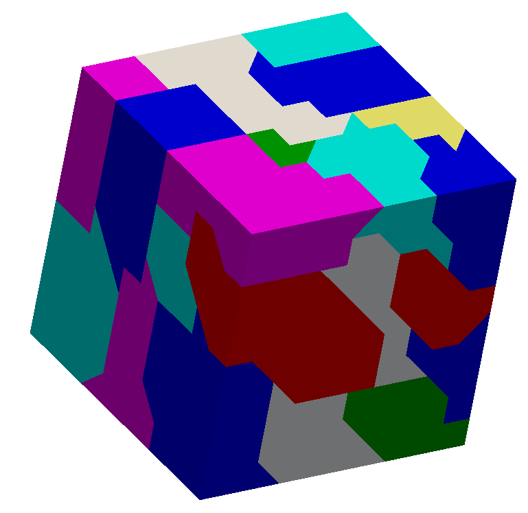
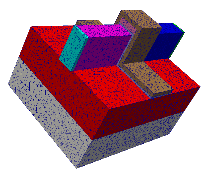
Figure 4.2: Two different geometries investigated in this study. (a) Cube geometry with exemplary independent sets of partitions denoted by the different colors. The mesh is partitioned using mt-METIS [190] and the partitions are colored using a Greedy graph coloring algorithm. (b) Tetrahedral mesh of an exemplary multi-material geometry of a double gate FinFET used in semiconductor device simulations: The different colors denote different material regions and can be seen as different independent sets.
4.3.2 Mesh Adaptation and Mesh Healing
After the partitioning of the input mesh and the coloring of the partitions, the next step of the presented mesh adaptation workflow is the adaptation itself (see Figure 4.1c). This process starts with the partitions located in the independent set with Color ID \(0\) (i.e., the set of partitions with color \(0\)). All partitions with the same Color ID are processed in parallel. In the first iteration, each partition creates its dedicated mesh data structure based on the proposed ideas in [29]. These data structures utilize lists storing the vertex coordinates, their adjacency relations, to which elements the vertices belong, and a list of vertex identifiers denoting the mesh elements. However, it is important to keep a valid link between the initial vertex indices and the local indices present in the partitions, in order to ensure proper mesh adaptation on interfaces between individual partitions. This connection is stored in unordered associative containers, e.g., unordered maps.
Obviously, if one partition adapts interface edges or facets, it is necessary to communicate these changes to all affected neighboring partitions. To achieve this, an additional linear data array, called outbox, is used. This outbox stores data about vertex insertions on the interface edges of adjacent partitions (see Figure 4.3). If a partition is inserting a vertex on an edge, the Partition ID of the affected neighboring partition, the global vertex indices of the two vertices building the split edge, and the local vertex index of the inserted vertex are stored in the outbox of the partition conducting the refinement.

Figure 4.3: Refinement and healing procedure using a so-called outbox for each partition P1 (yellow) and P2 (red). In the first step, the left partition P1 refines its elements including the interface to its neighbor P2 (green vertices and edges). Afterwards, the healing procedure conducted by the adjacent partition P2 integrates the inserted vertices (purple vertices) and subsequently refines the affected elements to sustain conformity (dashed purple edges).
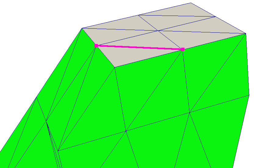
Figure 4.4: Example showing the healing issue. The green triangles are part of two different partitions as well as the two purple vertices; the gray triangles are only part of a single partition. Since the coarse-grained mesher stores only to which partitions the vertices belong and does not store any explicit edge or facet data, it can happen that an edge is mistakenly marked as part of an interface to a neighboring partition (purple edge).
To avoid data inconsistencies on the interfaces, the mesh adaptation is restricted on the partition’s boundary elements: If interface vertices belong to two or more partitions, only the partition with the smallest Partition ID is allowed to conduct actual mesh operations. Thus, over-refinement, i.e., two or more partitions inserting vertices on the interface, is prevented, yielding a homogeneous mesh refinement across the whole interface. Hence, for each vertex the Partition IDs of all partitions which the vertex belongs to are stored explicitly. However, due to this limited information it can happen that an edge is wrongly identified as an interface edge, as indicated in Figure 4.4. Nevertheless, even in such a case the partition conducting the refinement records the corresponding data in its outbox and the adjacent partition from one of the next Color IDs inserts this vertex during its mesh healing process. To resolve this issue of mistakenly inserted vertices, a check for dangling vertices is conducted which deletes all wrongly marked and inserted vertices after the healing step. This search and deletion method bypasses the adaptation of the implemented data structures and algorithms, as they do not contain explicit information on edges or facets. However, as the search and deletion approach is computationally trivial only negligible computational overhead is introduced.
For the mesh refinement itself two different options are used in the developed coarse-grained mesher. The first one is a mesh element subdivision scheme [195]. This template-based mesh refinement procedure is also included in the parallel mesh adaptation software PRAgMaTIc presented by Rokos et al. [29]. Its basic approach operates by splitting an edge into two by vertex insertion. A user-defined threshold for the maximum edge length is applied. Hence, each mesh element is refined depending on the number and position of its split edges following predefined templates for 2D and 3D mesh elements, i.e., triangles and tetrahedra. In order to obtain higher resolutions several iterations of the template-based mesh refinement have to be performed, as an edge can only be split once in a single iteration. The described template-based refinement algorithm is included in the coarse-grained mesher in a serial manner. Parallelism in the coarse-grained mesher is achieved due to the application of the algorithm on numerous partitions with the same Color ID in parallel.
The second mesh refinement procedure integrated in the presented coarse-grained approach is the serial Delaunay-based mesh generator TetGen [191] using its provided application programming interface (API). However, up to now TetGen is limited to isotropic mesh refinement of tetrahedra only, i.e., 3D mesh element refinement independent from the direction of the split edge.
One drawback of the Delaunay-based approach in the coarse-grained mesher is that the healing procedure utilizes the template-based refinement schemes. Therefore, the Delaunay-based refinement is restricted to the interior of the partitions, while the interface elements are adapted using the template-based approach. The reason for this is the fact that the data structures and algorithms used in the healing process are tailored to the template-based approach. If other mesh adaptation algorithms targeting also the boundary elements of a partition shall be included, the mesh healing data structures and algorithms have to be adapted accordingly.
After the mesh elements have been refined using the template-based approach, additional steps are required to ensure proper element quality. Thus, also the element swapping and smoothing routines provided in PRAgMaTIc are included. For the Delaunay-based algorithm, it is possible to utilize the quality enhancing algorithms directly via TetGen’s API during the mesh refinement process.
After finishing the mesh adaptation on all partitions of an independent set, every partition in the subsequent independent set has to heal its interface elements to sustain a conformal mesh as depicted in Figure 4.1d. In order to identify which interface elements have to be healed, a partition checks all outboxes of adjacent partitions, if vertices have been inserted. The coordinates of these vertices can be accessed using the information stored in the outbox, i.e., global vertex index, Partition ID of originating neighboring partition, and the two local vertex indices forming the original edge in the adjacent partition. If all adjacent outboxes have been checked, the template-based mesh refinement procedures are applied to heal interface elements. Subsequently, the shared-memory parallel mesh refinement procedure continues using either the template-based or the Delaunay-based mesh adaptation algorithm for the interior mesh elements (Figure 4.1c).
4.4 Evaluation
The presented coarse-grained mesher is evaluated using the 16 core benchmarking platform BP1 introduced in Chapter 2. The total number of partitions in this study is limited to 1,024 as higher numbers yield unreasonably high runtimes for the graph coloring step (even for the parallel approaches) compared to the mesh adaptation steps jeopardizing a meaningful and focused evaluation of the mesh adaptation step. Hence, benchmarks on BP2 are omitted in addition to the fact that several of the created independent sets are comprised of less than 64 partitions creating an unwanted computational bottleneck stemming from insufficient work in these small independent sets. This is especially the case for balanced coloring algorithms, as will be detailed in Section 4.4.2. Compilation of the code is conducted using Intel’s C++ compiler version 17.0.4 with optimization level -O3. Thread pinning with GOMP_CPU_AFFINITY enables thread-core affinity, thus preventing potential performance issues resulting from unnecessary thread migration.
4.4.1 Test Geometries and Benchmark Setup
In order to investigate the computational performance and the mesh quality of the presented coarse-grained mesher, two different test geometries are used. The first geometry is a 3D cube mesh as depicted in Figure 4.2a. This cube is investigated in two different resolutions, henceforth denoted as Small and Big. Small and Big are comprised of 6,000 and 93,750 tetrahedral mesh elements, respectively. As second test geometry a so-called double gate FinFET (Figure 4.2b), an exemplary and widely used structure occurring in TCAD simulations, is used, with initially 837,584 tetrahedral mesh elements.
The evaluation is conducted with both of the presented mesh adaptation schemes, the template-based and the Delaunay-based approach. For the template-based refinement the number of iterations is set to two to allow for an isolated and focused evaluation of the impact of a single iteration on quality and performance. The length threshold is set to 25% of the initial edge length for both cube meshes, Small and Big. The Delaunay-based scheme is also applied using two iterations and applying a volume constraint of 1% of the initial tetrahedron volume for both cube meshes. With these thresholds the two mesh adaptation schemes yield similar number of mesh elements enabling a proper comparison of both performance and element quality. However, for the FinFET only a single iteration of the template-based mesh refinement algorithm is conducted, using an edge length threshold of 25% of the initial edge length. For the volume constraint within the Delaunay-based approach a threshold of 13% is set for the benchmarks with the FinFET mesh. Similar to both cube meshes, these constraints are chosen such that they result in a comparable number of final mesh elements.1
Furthermore, a fixed number of partitions is applied, i.e., 1,024, in order to allow for a straightforward comparison of both performance and element quality. For the creation of the independent sets the Greedy and the Greedy-LU coloring algorithm are used to represent an unbalanced and a balanced coloring approach, respectively. Due to the rather small number of partitions with respect to the graph coloring operation, the use of the serial methods is favored in this study (see Chapter 3).
1 The limitation to one iteration is due to an already known bug (denoted as error code 2) in the Delaunay-based adaptation approach implemented in TetGen [50].
4.4.2 Partition Coloring
As stated above, the conducted benchmarks cover two different coloring strategies: A balanced (Greedy-LU) and an unbalanced Greedy approach. The different sizes of the created independent sets are shown in Figure 4.5. As expected and in accordance with the findings presented in Chapter 3, the Greedy graph coloring algorithm yields a skewed population of the independent sets, with the higher Color IDs comprised of less partitions than the smaller Color IDs. Hence, the higher Color IDs can be a potential bottleneck, in particular if the number of partitions is below the number of active threads. In this case, some threads will be left idle and thus limiting potential speedup. However, Figure 4.5 combined with the speedup results presented in Section 4.4.3 indicates that for the investigated meshes with 1,024 partitions, the speedup tends to be independent from the different coloring algorithms (see Section 4.4.3). This is due to the fact that most independent sets (even with higher Color IDs) consist of more partitions than the maximum number of 16 threads applied and thus minimizing load imbalance. Furthermore, potential speedup penalties occurring with an unbalanced coloring are partially alleviated by less mesh healing steps between the different independent sets, as the maximum number of used colors is usually below the number of colors produced by the balanced coloring approach.

4.4.3 Strong Scalability
Since the test meshes have a fixed number of initial mesh elements, i.e., a constant problem size, the strong scaling properties of the presented framework are investigated. For the benchmarks on BP1 (Section 2.4), the number of threads is increased from one to 16. Figure 4.6 presents the achieved speedups for the three different test meshes using 1,024 partitions. Additionally, benchmarks are conducted utilizing the original TetGen implementation [191] in order to provide a baseline for the overall performance of the presented coarse-grained mesher.


Figure 4.6: Strong scaling results for the two cube geometries after two iterations using 1,024 partitions and for the FinFET geometry after a single mesh adaptation iteration also using 1,024 partitions. The dotted lines show the data obtained utilizing a balanced coloring prior to the application of the different adaptation algorithms. Additionally, the left column shows the serial runtime of the original TetGen implementation (TetGen Orig.). All benchmarks are performed on BP1 with a maximum of 16 threads.
The Small cube mesh is adapted in two iterations, resulting in an increase of tetrahedral mesh elements from 6,000 to nearly 315,000. The highest speedup of 4.6 is achieved by applying the template-based mesh adaptation approach with 16 threads. For the Delaunay-based method a speedup of 7.8 with 16 threads is obtained. However, the total runtimes of the two adaptation approaches prove that for this relatively small mesh the template-based approach outperforms the Delaunay-based approach, regardless of the number of active threads. Additionally, the independent sets created with the Greedy-LU coloring algorithm yield slightly faster runtimes. Using such small problem sizes as with the Small cube mesh also shows that mesh adaptation is an inherently memory-bound problem [144]. In addition, the introduced overhead of the developed coarse-grained mesher, e.g., the domain decomposition and the mesh healing steps, influences the overall performance resulting in inferior performance of the developed method compared to TetGen for small thread counts (see left column of Figure 4.6). A possible solution is to increase the efficiency of the partitioning or the mesh healing step, as the Delaunay-based mesh adaptation approach utilizes the same adaptation routines as TetGen.
A detailed evaluation of the speedup data obtained for the Small cube mesh shows an interesting behavior: The speedup for the balanced Delaunay-based refinement approach using two threads is slightly above two. The reason for this behavior is similar to the discussion presented in Chapter 3: The Delaunay algorithm has a complexity of \(\mathcal {O}(n \log n)\), explaining the superlinear speedup following Equation 3.6. Note, however, that this superlinear speedup is usually not observable as imperfect load balancing or limited memory bandwidth limit the overall speedup [129].
The two bigger problems in this study, i.e., the Big cube and the FinFET mesh, are refined from initially 93,750 and 837,584 to about 5,500,000 and 6,600,000 tetrahedra, respectively. The obtained maximum speedups with 16 threads for the Big cube mesh are 5.2 for the template-based method and 8.6 for the Delaunay-based method. The speedups for the FinFET with 16 threads peak at 5.1 and 6.8 using the template-based and the Delaunay-based refinement, respectively. As already hinted, the memory-bound nature of the mesh adaptation problem restricts the obtainable speedup [144]. A comparison of the two different mesh adaptation techniques proves that for the bigger problem sizes in this study, the Delaunay-based method outperforms the template-based approach, since for the latter technique the element swapping and smoothing require more time to achieve proper element quality than the Delaunay-based approach. Additionally, the overall computational performance for the whole set of test meshes is limited by memory bandwidth for thread counts above eight [196]. Furthermore, NUMA effects had an additional influence on the performance, particularly for the case of 16 threads, were both CPUs of BP1 were utilized.
4.4.4 Mesh Quality
The influence of the mesh healing process, especially the constraints on the interface element refinement, is evaluated utilizing two different quality metrics implemented in the Verdict Geometry Quality Library [54]. As first metric the so-called edge ratio, as defined in Equation 2.14, is used. As already stated in Section 2.2.1 an equilateral tetrahedron yields an optimal element quality of \(1\). In addition to the edge length, the minimum dihedral angle of a tetrahedron acts as second quality metric, with an optimum value of \(70.53^\circ \).
The initial quality distributions for all three test meshes are shown in Figure 4.7. As the initial discretization of the cube geometry is achieved using highly homogeneous non-optimal tetrahedra, the edge ratios and the minimal dihedral angles for both resolutions are similar, with prominent peaks for the angles at \(35.3^\circ \), \(45.0^\circ \), \(54.7^\circ \), and \(60.0^\circ \). The resulting distributions obtained using the two different refinement methods are depicted in Figure 4.8 together with the quality results from TetGen. All quality distributions resulting from the template-based approach are shown in blue, the green bars denote the distributions from the Delaunay-based approach, and qualities obtained from TetGen are depicted using pink bars.
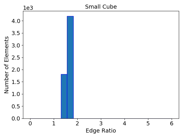
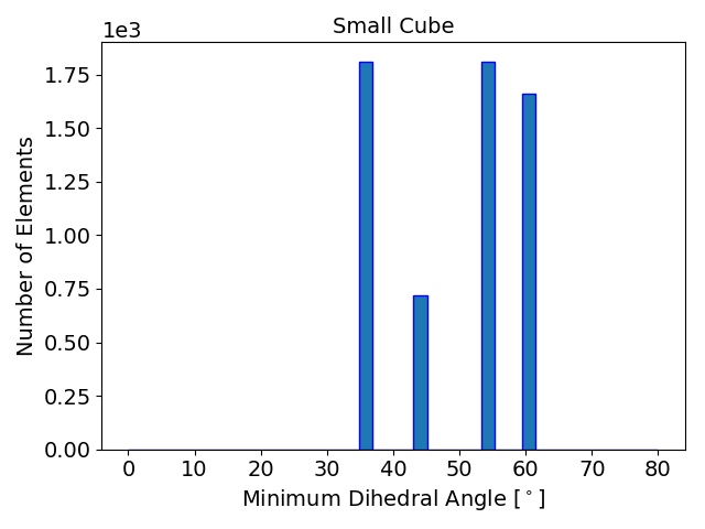
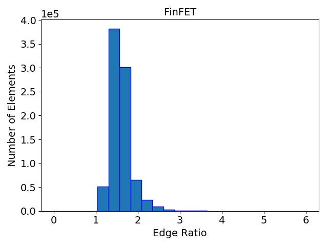
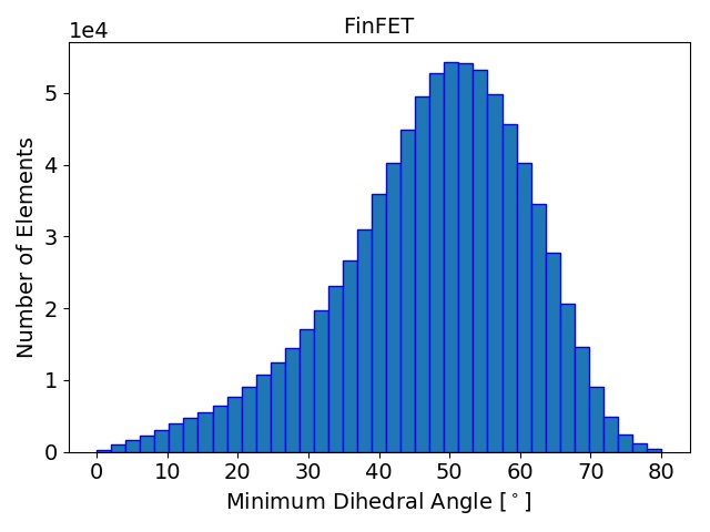
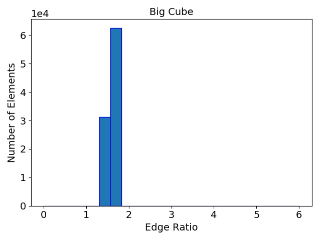
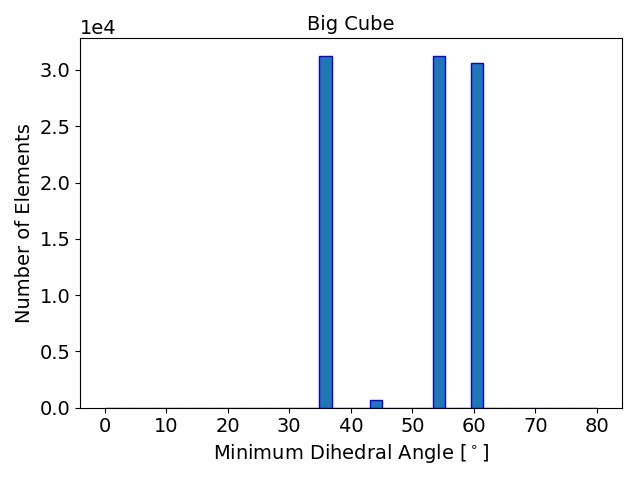
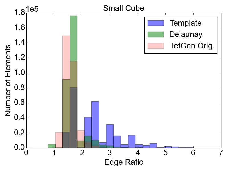
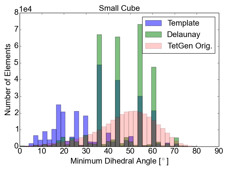
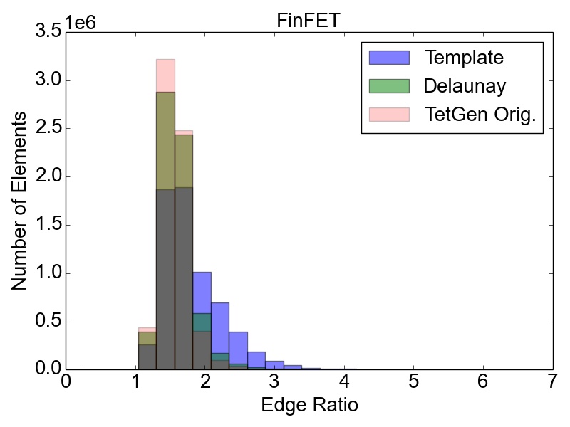
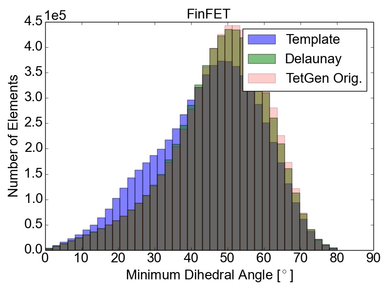
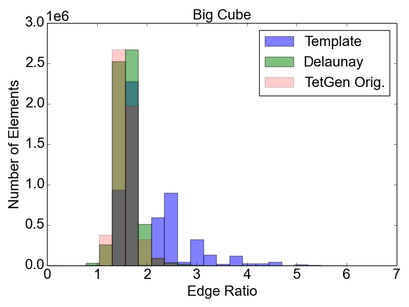
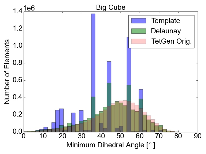
Figure 4.8: Resulting mesh quality distributions for the Small and Big cube meshes after two refinement iterations using 1,024 partitions and for the FinFET after one refinement iteration also using 1,024 partitions. The left column depicts the edge ratios and the right column the minimum dihedral angles occurring in the tetrahedra.
Figure 4.8 shows that the obtained element qualities using the template-based refinement algorithms are inferior to those obtained utilizing the Delaunay-based approach: A higher number of mesh elements with smaller dihedral angles as well as with larger edge ratios. This is because the template-based approach only splits already existing mesh elements by vertex insertions on edges of the tetrahedra. Additionally, quality enhancing algorithms (i.e., vertex smoothing and edge swapping) are only applied after the actual edge splitting also limiting the possible increase of the overall mesh element qualities. Contrary to this method, vertex insertion in the Delaunay-based adaptation procedure is not limited to already existing edges. Thus, superior mesh quality is achieved for all test geometries, as the optimal vertex position during the mesh refinement can be used for inserting a new mesh vertex (see Figure 4.8). However, both cube meshes have accumulations of mesh elements with similar minimum dihedral angles at \(35.3^\circ \), \(45.0^\circ \), \(54.7^\circ \), and \(60.0^\circ \) in the final mesh. These peaks stem from the initial meshes, as shown in Figure 4.7, and are preserved throughout the adaptation process in the developed coarse-grained mesher due to the template-based refinement of the boundary elements in the partitions.
This is also the reason why for small sized problems like the Small cube mesh, the quality output of the original TetGen implementation, i.e., better minimum dihedral angles and edge ratios, outperforms the coarse-grained mesher. Regarding the other two test meshes, similar element qualities are obtained, indicating that the constraints introduced by the mesh healing procedure have decreasing effect on the quality distributions with increasing problem size.
4.5 Summary and Conclusion
In this chapter a new coarse-grained shared-memory parallel mesh adaptation framework, based on adapting independent sets of partitions, was presented. The framework is able to conduct the mesh refinement using two different serial methods: A template-based and a Delaunay-based algorithm. A major advantage of the presented approach is its ability to utilize highly tuned available serial mesh adaptation algorithms in a shared-memory parallel environment. However, the refinement operations on the boundary elements of partitions are limited, such that only the partition with the lowest Color ID is allowed to process these elements. This prevents over-refinement of the interface elements as well as data inconsistencies. For the evaluation of the introduced framework two different test geometries were used, a cube and a FinFET. In order to investigate the performance and the quality output of the two different refinement algorithms, the resulting meshes were analyzed with respect to their edge ratios and minimum dihedral angles. To assess the computational performance of this new framework, a strong scaling analysis, i.e., with constant problem size, was performed. The reported speedups peak at 8.6 for 16 threads with the Delaunay-based algorithm. Furthermore, the conducted study showed that the shared-memory parallel approach outperforms TetGen in some cases. Regarding the element quality, the presented results indicate that applying the Delaunay-based technique yields higher quality output than the template-based method. Nevertheless, the latter algorithm is up to now the only solution for anisotropic mesh refinement in the presented coarse-grained mesher and basis for the interface adaptation.
Potential extensions for the novel coarse-grained mesher could focus on the investigation and implementation of different mesh healing options, in order to alleviate the restriction to the template-based approach, which limits the final mesh element quality. Furthermore, it is of interest to investigate different domain decomposition methods to improve the load-balancing of the subsequently conducted mesh adaptation operations. Additionally, including further mesh adaptation operations, e.g., mesh coarsening, would widen the applicability and potentially increase the quality of the resulting mesh elements produced with the developed coarse-grained mesher.